
System and method for dynamically controlling the stability of an articulated vehicle

a technology of dynamic control and stability, which is applied in the direction of braking system, cycle equipment, instruments, etc., can solve the problems of static stability limits, limited ability to control the cg position and/or stability limits of traditional ground vehicles (both manned and unmanned), and inability to control the stability limi

Inactive Publication Date: 2004-11-25
LOCKHEED MARTIN CORP
View PDF99 Cites 45 Cited by
  • Summary
  • Abstract
  • Description
  • Claims
  • Application Information

AI Technical Summary

Problems solved by technology

However, as objects become more and more complex, so do the systems and methods to control their motion.
For each additional component, additional relationships are created, thus making the systems and methods to control their motion more and more complex.
Aside from manipulating on-board payloads, the ability to control the CG position and / or the stability limits of traditional ground vehicles (both manned and unmanned) is limited.
Stability limits are static in conventional vehicles but may change in articulated vehicles due to changes in a vehicles footprint.
Conventional vehicles simply lack enough unsprung mass or controlled range of motion of offboard components (e.g., suspension components) to appreciably change the CG and / or stability limits of the vehicle.
While conventional control systems exist that address stability, these systems typically are limited to monitoring the vehicle's CG relative to its stability limits and either initiating warning devices or countersteering in the event stability limits are near breaching.
Controlling the motion and attitude of more complex vehicles, such as articulated, ground vehicles, cannot generally be simplified in the same ways as these conventional ground vehicles.
These controllers and methodologies typically focus on the statically determinate case of the system being controlled, failing to address the overall dynamic properties of the system.
Such controllers and methodologies are, therefore, not well suited for controlling articulated vehicles.

Method used


Image

  • System and method for dynamically controlling the stability of an articulated vehicle
  • System and method for dynamically controlling the stability of an articulated vehicle
  • System and method for dynamically controlling the stability of an articulated vehicle

Examples


Embodiment Construction

[0034] Illustrative embodiments of the invention are described below. In the interest of clarity, not all features of an actual implementation are described in this specification. It will of course be appreciated that in the development of any such actual embodiment, numerous implementation-specific decisions must be made to achieve the developer's specific goals, such as compliance with system-related and business-related constraints, which will vary from one implementation to another. Moreover, it will be appreciated that such a development effort, even if complex and time-consuming, would be a routine undertaking for those of ordinary skill in the art having the benefit of this disclosure.

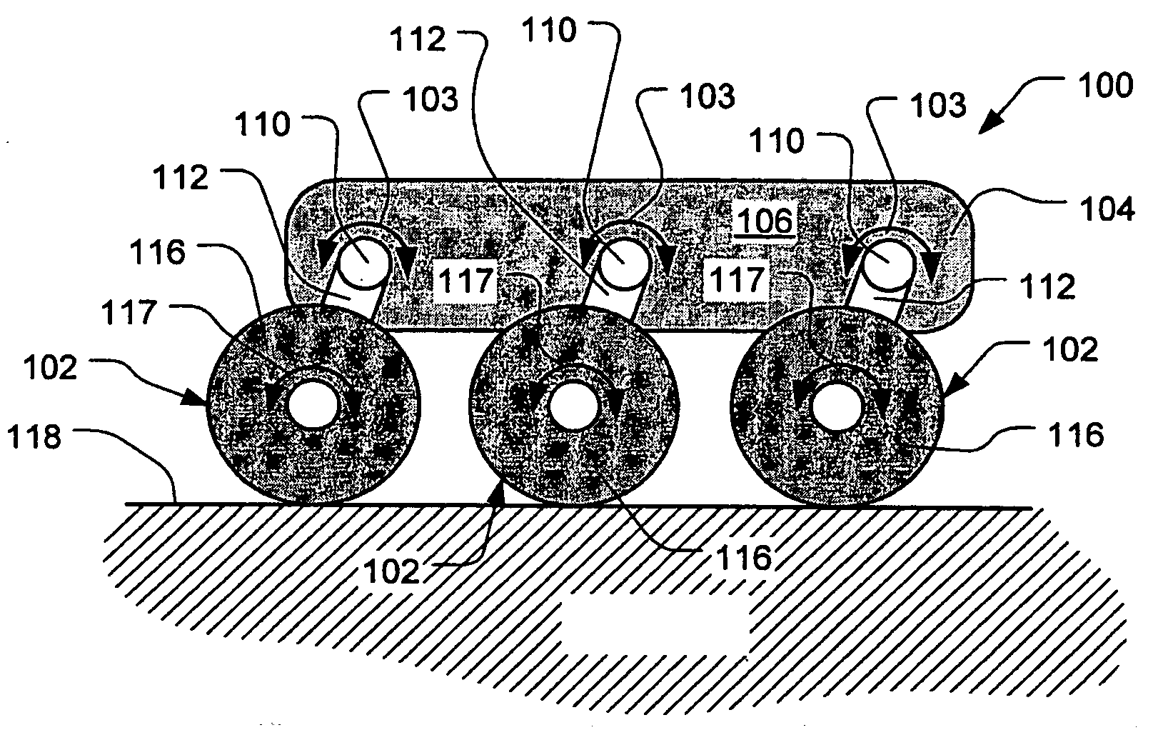
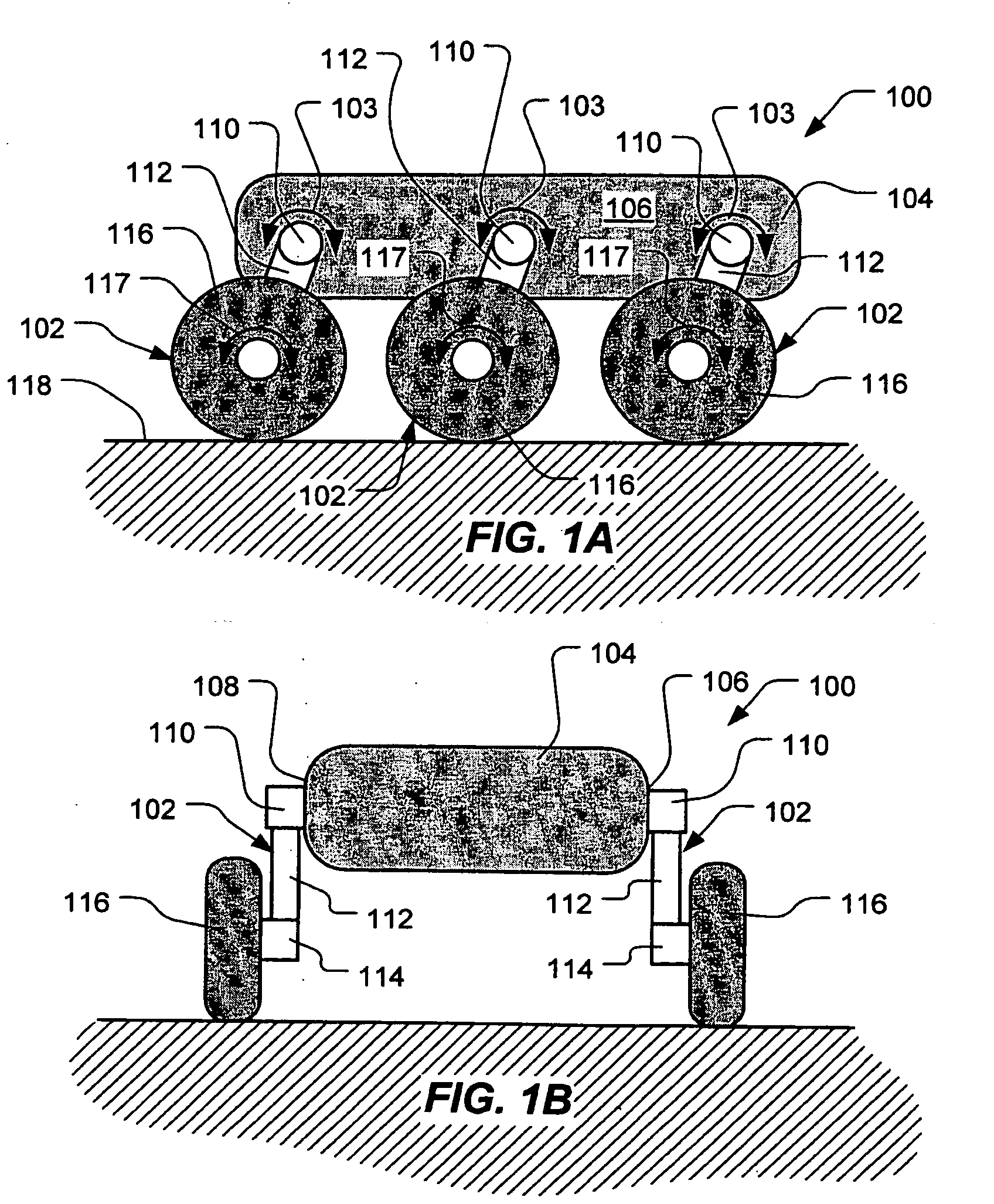
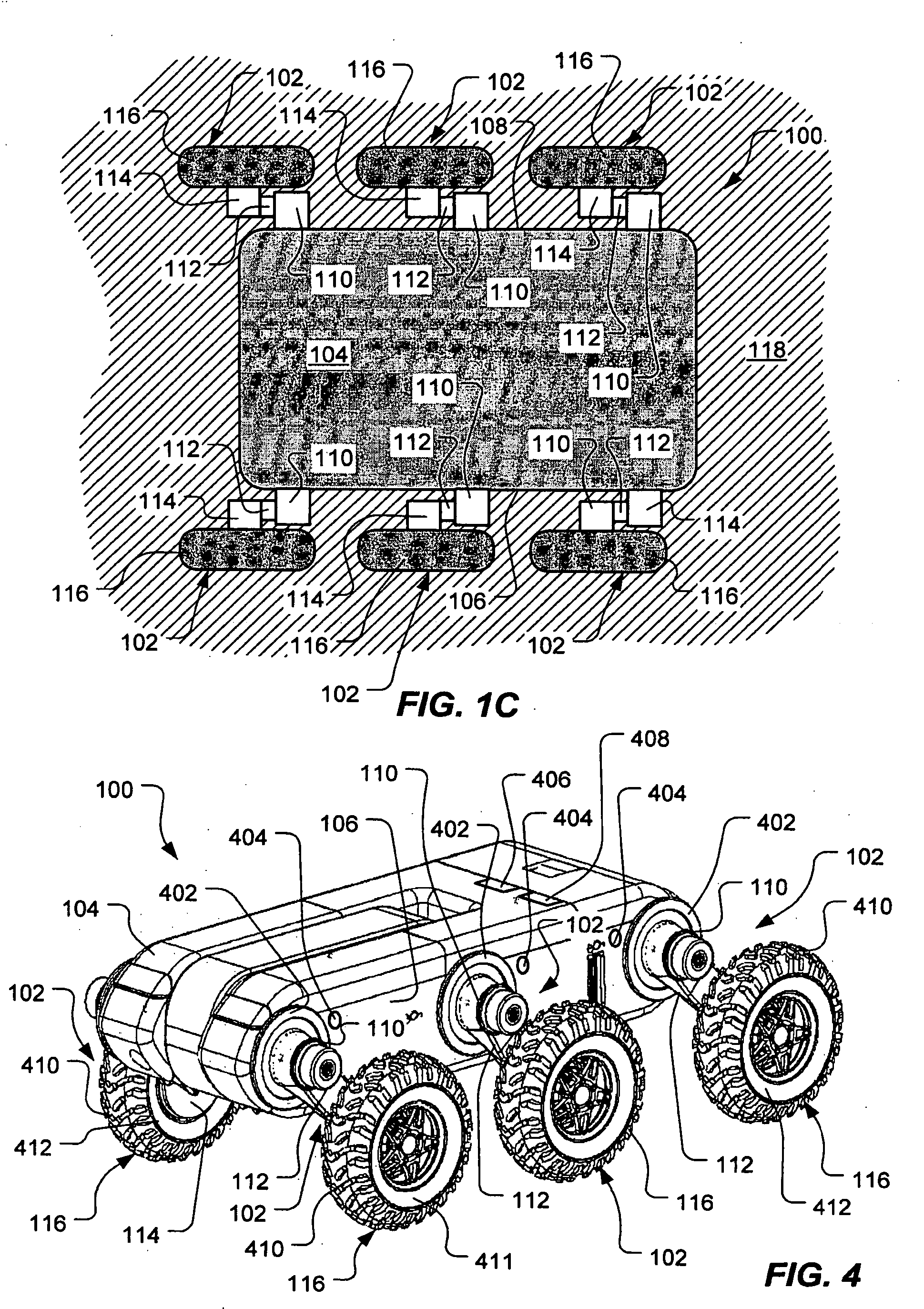
[0035] The present invention pertains to dynamically controlling the stability of a ground vehicle, and, more particularly, to dynamically controlling the CG and / or the stability limits of a ground vehicle to affect its stability. For example, according to the present invention, the stability of...


PUM


Abstract

A method of controlling stability of a vehicle having an articulated suspension includes determining at least one dynamic property of the vehicle and manipulating the articulated suspension based on the at least one dynamic property to affect the stability of the vehicle. A method of controlling stability of a vehicle having an articulated suspension includes determining a damping scenario and adjusting damping levels of a plurality of active dampers of the articulated suspension. A method of controlling stability of a vehicle having an articulated suspension includes determining a load on each of a plurality of wheel assemblies of the articulated suspension and manipulating at least one component of the vehicle to affect at least one of a center of gravity of the vehicle and the vehicle's stability limits.

Description

[0001] The earlier effective filing date is claimed of co-pending U.S. Provisional Application Ser. No. 60 / 449,271, entitled "Unmanned Ground Vehicle," filed Feb. 21, 2003, in the name of Michael S. Beck, et al. (Docket No. 2063.005190 / VS-00607), for all common subject matter. Further, the earlier effective filing date is claimed of co-pending U.S. application Ser. No. 10 / 639,278, entitled "Vehicle Having an Articulated Suspension and Method of Using Same", filed Aug. 12, 2003, in the name of Michael S. Beck et al. (Docket No. 2063.004600 / VS-00582), for all common subject matter.[0002] 1. Field of the Invention[0003] This invention relates to a system and method for controlling the stability of a vehicle and, in particular, to a system and method for controlling the stability of an articulated vehicle.[0004] 2. Description of the Related Art[0005] Controlling motion in basic objects is quite simple. However, as objects become more and more complex, so do the systems and methods to c...

Claims


Application Information

Patent Timeline
Patent Type & Authority Applications(United States)
IPC IPC(8): B60G17/016B60G17/06B60K7/00B60K17/04B60K17/356B60T1/06
CPCB60G17/016B60G17/06B60G2200/132B60G2202/22B60G2202/23B60G2300/07B60G2400/051B60G2400/0511B60G2400/0512B60G2400/106B60G2400/204B60G2400/61B60G2400/63B60G2400/821B60G2600/184B60G2800/01B60G2800/915B60K7/0007B60K17/046B60K17/356B60K2007/0038B60K2007/0092B60T1/062
Inventor BECK, MICHAEL S.CONRAD, KEVIN L.
Owner LOCKHEED MARTIN CORP
Learn More