Motion vector detection method
a detection method and motion vector technology, applied in signal generators with optical-mechanical scanning, color television with bandwidth reduction, signal systems, etc., can solve the problems of inability to estimate optimal motion vectors, inability to take into account the change of pixel values due to fade,
- Summary
- Abstract
- Description
- Claims
- Application Information
AI Technical Summary
Benefits of technology
Problems solved by technology
Method used
Image

Examples
first embodiment
[0107] The following describes the moving picture coding apparatus according to the present invention with reference to the diagrams.
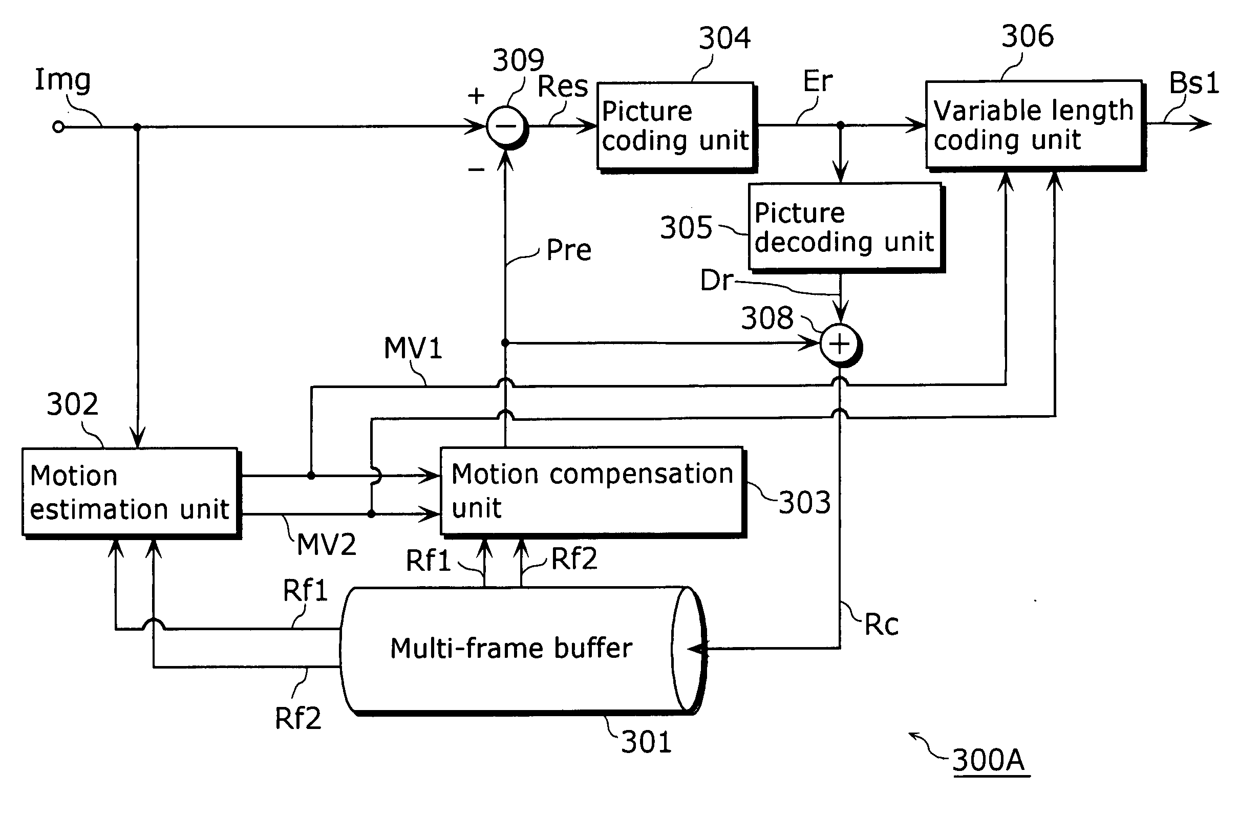
[0108] FIG. 9 is a block diagram showing the structure of the moving picture coding apparatus 300A according to the present embodiment.
[0109] The moving picture coding apparatus 300A of the present embodiment is composed of a multi-frame buffer 301, a motion estimation unit 302, a motion compensation unit 303, a picture coding unit 304, a picture decoding unit 305, a variable length coding unit 306, an adder 308 and a subtracter 309. Such moving picture coding apparatus 300A estimates optimal motion vectors and codes them. The motion estimation unit 302 estimates optimal motion vectors MV1 and MV2 for the current block in a current frame Tf to be coded indicated by a picture signal Img based respectively on reference frames Rf1 and Rf2 which are read out from the multi-frame buffer 301.
[0110] When a forward interpolation prediction is employed, the mot...
second embodiment
[0150] The following describes the moving picture decoding apparatus according to the second embodiment of the present invention with reference to the diagrams.
[0151] FIG. 15 is a block diagram showing the structure of the moving picture decoding apparatus 300B according to the present embodiment.
[0152] The moving picture decoding apparatus 300B described in the present invention is composed of a variable length decoding unit 336, a motion compensation unit 333, a picture decoding unit 335, a multi-frame buffer 331 and an adder 339. Such moving picture decoding apparatus 300B decodes the moving picture coded by the moving picture coding apparatus 300A.
[0153] The variable length decoding apparatus 336 obtains the coded picture signal Bs1, performs variable length decoding on it, and outputs the coded residual signal Er as well as the motion vectors MV1 and MV2. It should be noted that when the differentials between the respective motion vectors MV1, MV2 and the predicted values of th...
third embodiment
[0159] The following describes the moving picture coding apparatus according to the third embodiment of the present invention with reference to the diagrams.
[0160] FIG. 16 is a block diagram showing the structure of the moving picture coding apparatus 400A according to the present embodiment.
[0161] The moving picture coding apparatus 400A according to the present embodiment is composed of a multi-frame buffer 401, a motion estimation unit 402, a motion compensation unit 403, a picture coding unit 404, a picture decoding unit 405, a variable length coding unit 406, an adder 408 and a subtracter 409. Such moving picture coding apparatus 400A estimates optimal motion vectors and codes them in the same manner as shown in the first embodiment,.
[0162] The multi-frame buffer 401, the motion compensation unit 403, the picture coding unit 404, the picture decoding unit 405, the adder 408 and the subtracter 409 of the present embodiment respectively have the same function and structure as the...
PUM
 Abstract
Description
Claims
Application Information
 - Generate Ideas
- Intellectual Property
- Life Sciences
- Materials
- Tech Scout
- Unparalleled Data Quality
- Higher Quality Content
- 60% Fewer Hallucinations
Browse by: Latest US Patents, China's latest patents, Technical Efficacy Thesaurus, Application Domain, Technology Topic, Popular Technical Reports.
© 2025 PatSnap. All rights reserved.Legal|Privacy policy|Modern Slavery Act Transparency Statement|Sitemap|About US| Contact US: help@patsnap.com