Ejector cycle
- Summary
- Abstract
- Description
- Claims
- Application Information
AI Technical Summary
Benefits of technology
Problems solved by technology
Method used
Image

Examples
first embodiment
[0028] (First Embodiment)
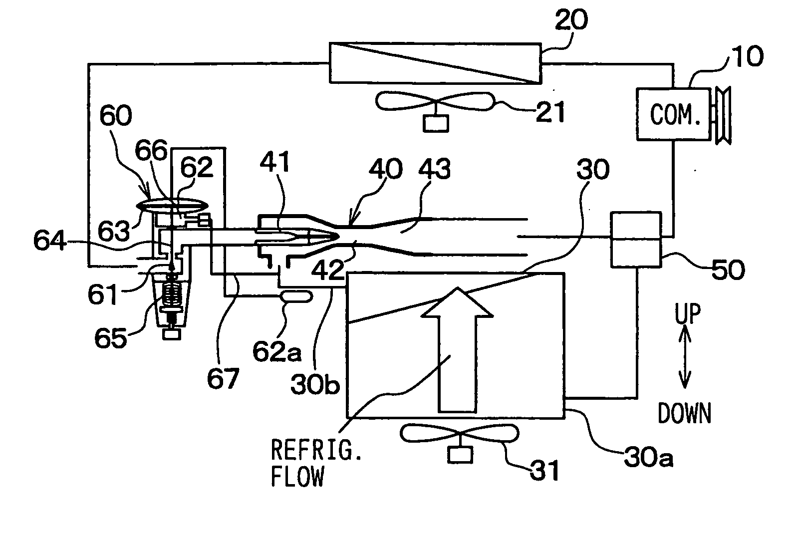
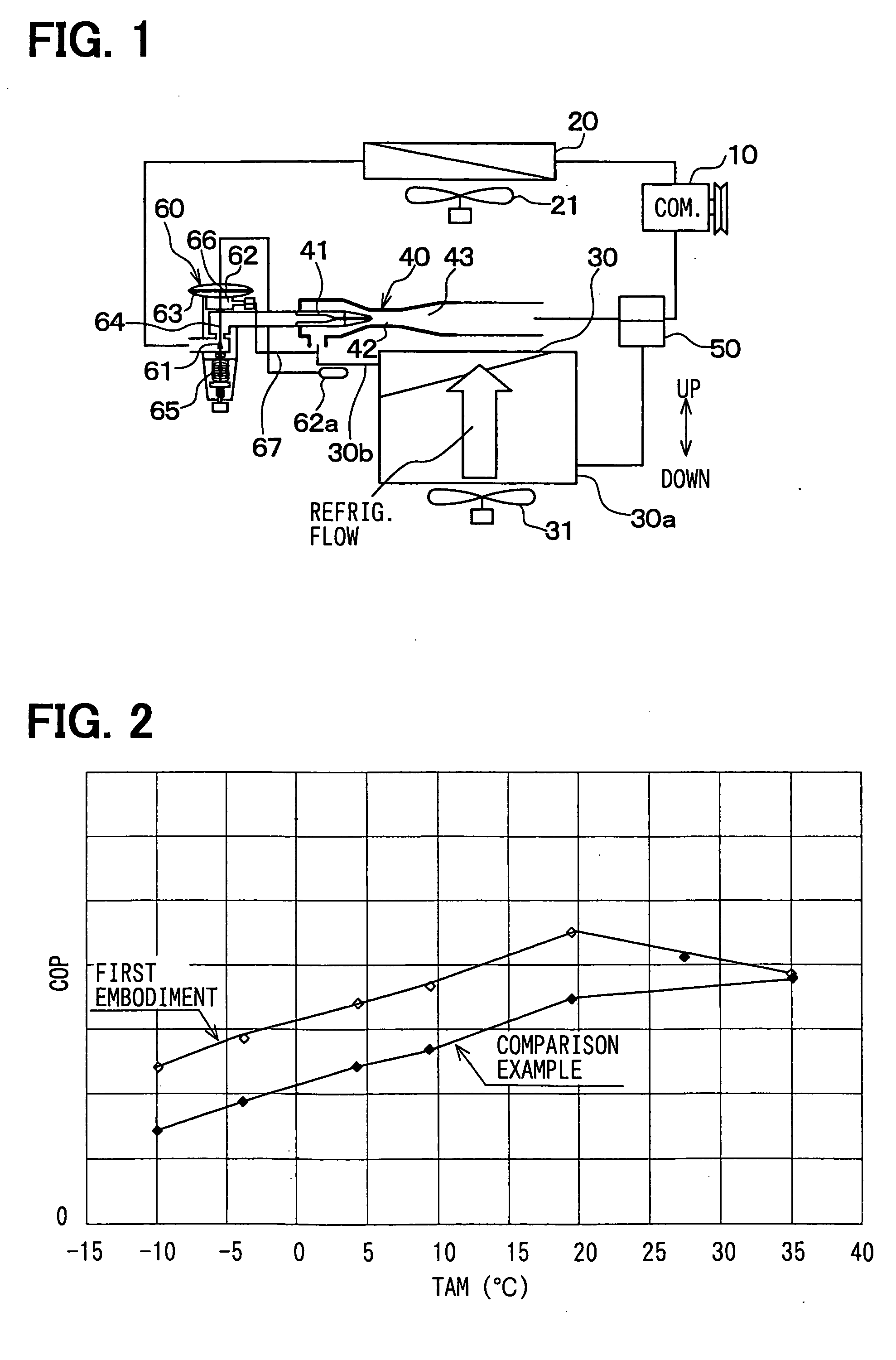
[0029] In the first embodiment, an ejector cycle is typically used as a vapor compression refrigerator for a showcase for cooling and refrigerating foods and drinks or as a vapor compression refrigerator mounted in a vehicle for transporting foods and drinks while keeping at a cooling or refrigerating state.
[0030] In the ejector cycle of FIG. 1, a compressor 10 is an electric compressor or a compressor driven by a vehicle engine, for sucking and compressing refrigerant circulated in the ejector cycle. A condenser 20 (cooler, radiator) is a high-pressure heat exchanger for cooling high-temperature and high-pressure refrigerant discharged from the compressor 10 by performing heat-exchange operation between outside air and the high-temperature and high-pressure refrigerant. A condenser fan 21 is an electrical blower for blowing outside air (cooling medium, cooling air) to the condenser 20.
[0031] Further, an evaporator 30 is a low-pressure heat exchanger for coo...
second embodiment
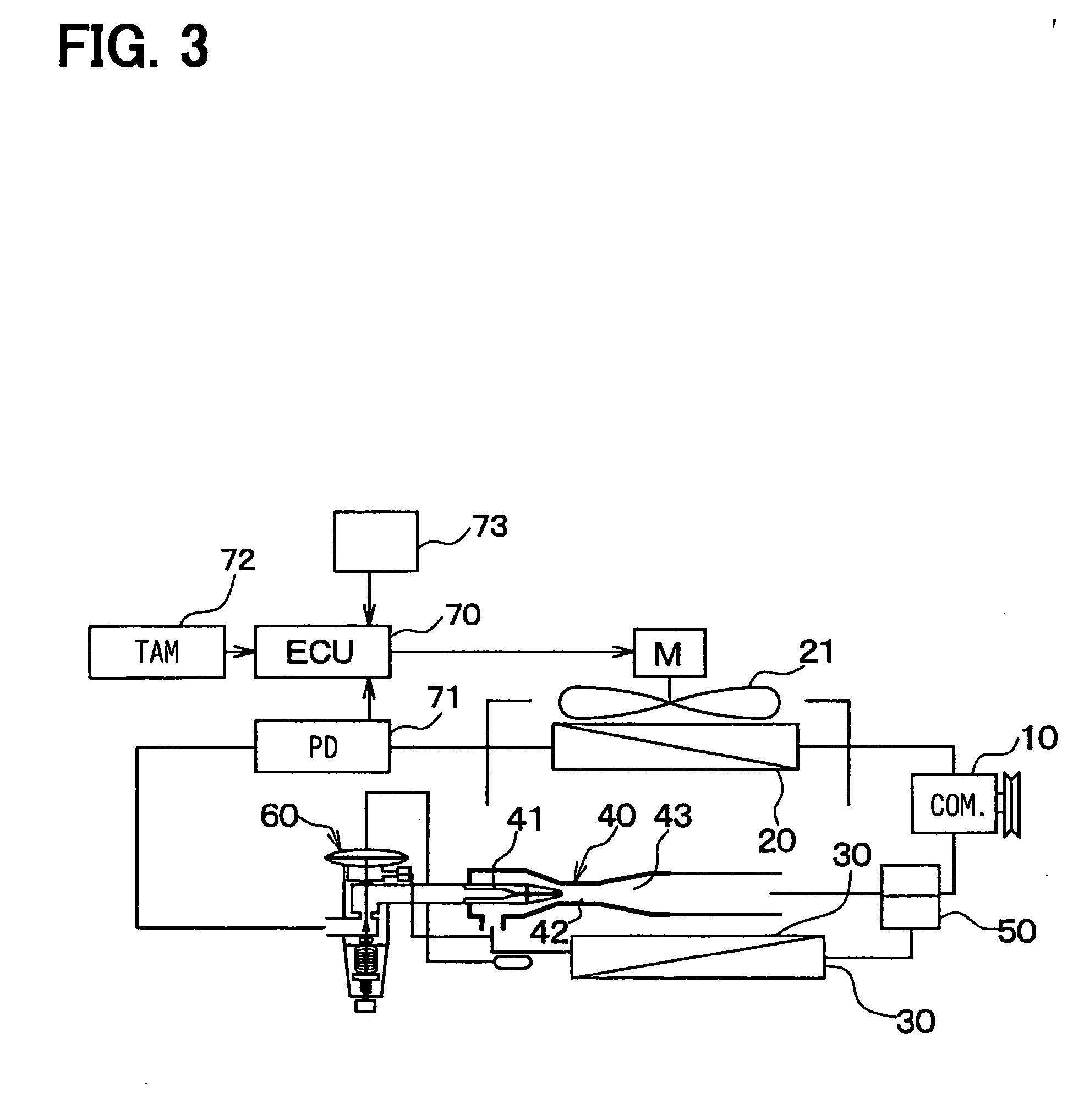
[0052] (Second Embodiment)
[0053] The second embodiment of the present invention will be now described with reference to FIGS. 3 to 7. In the second embodiment, as shown in FIG. 3, a pressure sensor 71 is provided at a refrigerant outlet side of the condenser 20, for detecting a pressure (PD) of high-pressure refrigerant before being decompressed. Further, an outside air temperature sensor 72 is provided to detect a temperature of cooling air supplied to the condenser 20, that is, to detect an outside air temperature TAM. The condenser fan 21 is controlled so that an air blowing amount (fan motor output) from the condenser fan 21 is decreased in accordance with a decrease of the temperature of cooling air (outside air) supplied to the condenser 20. By controlling the condenser fan 21, the pressure of the high-pressure refrigerant to be introduced to the nozzle 41 can be controlled to a pressure more than a predetermined value. That is, a refrigerant state to flow into the nozzle 41 i...
third embodiment
[0071] (Third Embodiment)
[0072] The third embodiment of the present invention will be now described with reference to FIG. 8. As described in the second embodiment, the high-pressure side refrigerant pressure PD has a relationship with the outside air temperature TAM. In the third embodiment, the air amount blown from the condenser fan 21, that is, the voltage applied to the fan motor of the condenser fan 21 is controlled based on the high-pressure side refrigerant pressure PD detected by the pressure sensor 71.
[0073] Next, a control operation of the condenser fan 21 according to the third embodiment will be now described with reference to FIG. 8.
[0074] The flow diagram of the control program shown in FIG. 8 starts when the main switch (start switch) of the control panel 73 is turned on, and the flow diagram of the control program shown in FIG. 8 stops when the main switch (start switch) of the control panel 73 is turned off. At step S10, the condenser fan 21 is operated to blow air...
PUM
 Abstract
Description
Claims
Application Information
 - Generate Ideas
- Intellectual Property
- Life Sciences
- Materials
- Tech Scout
- Unparalleled Data Quality
- Higher Quality Content
- 60% Fewer Hallucinations
Browse by: Latest US Patents, China's latest patents, Technical Efficacy Thesaurus, Application Domain, Technology Topic, Popular Technical Reports.
© 2025 PatSnap. All rights reserved.Legal|Privacy policy|Modern Slavery Act Transparency Statement|Sitemap|About US| Contact US: help@patsnap.com