Refrigerating system of air conditioner

An air-conditioning refrigeration and condenser technology, applied in refrigerators, refrigeration components, refrigeration and liquefaction, etc., can solve problems such as easy retention of liquid refrigerant and lubricating oil, no mention of the length design of the liquid return pipe, and unfavorable system energy saving. , to eliminate the phenomenon of liquid storage, improve the circulation of refrigerant, and improve the effect of operation reliability

Active Publication Date: 2022-07-12
GREE ELECTRIC APPLIANCES INC
View PDF7 Cites 0 Cited by
  • Summary
  • Abstract
  • Description
  • Claims
  • Application Information

AI Technical Summary

Problems solved by technology

In order to prevent the liquid refrigerant in the evaporator from entering the compressor, the return air main pipe is usually connected to the highest possible liquid level in the gas collection pipe of the evaporator, but this will easily cause liquid refrigerant and gas to remain in the bottom of the gas collection pipe. Lubricating oil, because the flow of refrigerant in the bottom branch is small and the flow rate is low, it cannot carry enough liquid refrigerant and / or lubricating oil to flow upward. After running for a long time, it is easy to accumulate liquid refrigerant and retain part of the lubrication at the bottom of the gas collection header Oil
When the height of these liquids gradually rises, the bottom branch is easy to form a liquid seal, and the flow of refrigerant that can pass through is less, resulting in the formation of a "liquid storage" phenomenon at the bottom of the evaporator. Obviously, these liquid refrigerants will also hold more lubrication inside oil, it is easy to cause insufficient refrigerant circulation and insufficient oil return in the refrigeration system
[0003] In the related art, it is proposed to connect the liquid return pipe to the return air main pipe at the bottom of the gas collecting pipe assembly of the evaporator, so as to suck the liquid retained at the bottom of the gas collecting pipe through the action of pressure difference Returning to the compressor, but there are some problems in this method: 1) After the machine is shut down, the high and low pressures of the air-conditioning and refrigeration system will gradually achieve pressure balance, and the high-pressure end will squeeze the liquid refrigerant to accumulate in the evaporator, and the evaporator at the bottom Refrigerant liquid is easy to return directly to the suction pipe of the compressor through the oil return pipe, or even reach the oil pool of the compressor, which will cause the compressor to start with liquid in the next start-up process, easy to liquid shock, etc.; 2) The liquid return pipe is stipulated The size of the pipe diameter does not mention the length design of the liquid return pipe, only the design principle of the pipe diameter of the liquid return pipe is proposed
In actual design, the diameter and length of the liquid return pipe need to be determined according to the pressure difference and the return flow. The smaller the return liquid pipe diameter or the longer the liquid return pipe, the smaller the return flow. It may not be possible to achieve safe return flow, and eventually it will Cause refrigerant liquid and lubricating oil to partially accumulate at the bottom of the evaporator
In some technical solutions, the oil return solenoid valve is used to add a liquid return pipe and a one-way valve to realize oil return and liquid return at the same time, but the expansion work of throttling and decompression of the oil return capillary is not recycled, which is not conducive to energy saving of the system
[0004]In addition, the refrigerant liquid before throttling often carries gas, and the gas is easy to affect the throttling effect and operation stability of the throttling device, so it is necessary to ensure that pure liquid enters Throttling device, so it is necessary to perform throttling expansion after separating gas and liquid

Method used


Image

  • Refrigerating system of air conditioner
  • Refrigerating system of air conditioner

Examples


Embodiment Construction

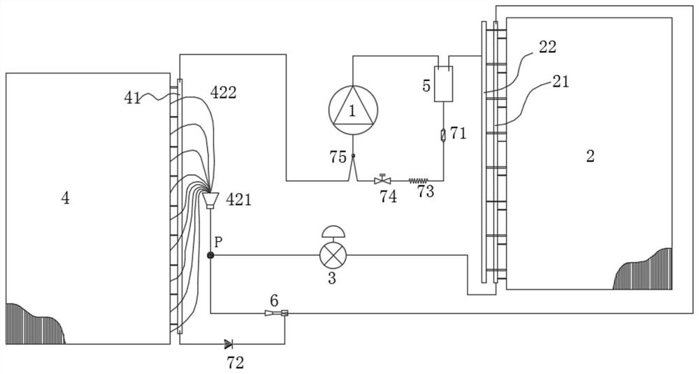
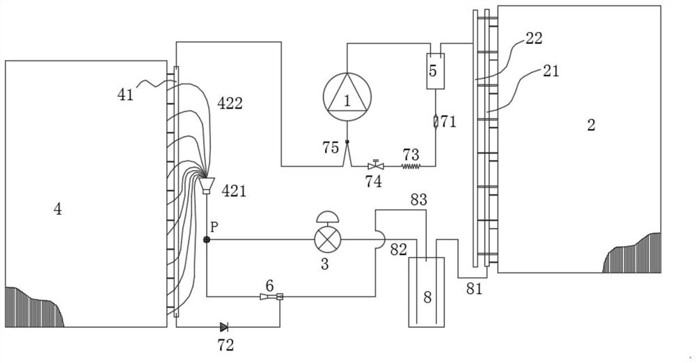
[0021] see in combination figure 1 and figure 2 As shown, according to an embodiment of the present invention, an air conditioning and refrigeration system is provided, including a compressor 1, a condenser 2, a first throttle element 3 (specifically, an expansion valve), and an evaporator 4. The compressor 1, The condenser 2, the first throttling element 3, and the evaporator 4 are connected in sequence to form a refrigeration cycle, and further includes an ejector 6, which can connect the liquid collecting pipe 21 of the condenser 2 to the first section. Outlet line of flow element 3 (eg figure 1 and figure 2 The accumulated liquid in the evaporator 4 is mixed and pressurized at the outlet of the ejector 6 and enters the evaporator 4 under the action of the pressure difference between the P point position in the above. In this technical solution, the high-pressure refrigerant fluid (gas phase or liquid phase) in the header 21 enters the nozzle from the inlet of the ejec...


PUM


Abstract

The invention provides an air conditioner refrigerating system which comprises a compressor, a condenser, a first throttling element, an evaporator and an ejector, and the compressor, the condenser, the first throttling element and the evaporator are sequentially connected to form a refrigerating cycle. The ejector can mix and pressurize accumulated liquid in the evaporator at an outlet of the ejector to enter the evaporator under the action of the pressure difference between a liquid collecting pipe of the condenser and an outlet pipeline of the first throttling element. According to the invention, the expansion work of throttling and pressure reduction of the ejector is fully recycled, the system is more energy-saving, a corresponding control component is not required to be designed for accumulated liquid suction, the phenomenon that liquid is easily stored at the bottom of the evaporator is effectively avoided, the operation reliability of the refrigerating system is improved, and the accumulated liquid is sucked to participate in a refrigerating cycle, so that the refrigerating efficiency is improved. And the refrigerant circulation volume of the evaporator is improved.

Description

technical field [0001] The invention belongs to the technical field of air conditioning, and in particular relates to an air conditioning refrigeration system. Background technique [0002] In the current vapor compression refrigeration cycle, some refrigeration systems are not designed with gas-liquid separators. In order to prevent the liquid refrigerant in the evaporator from entering the compressor, the return gas main pipe is usually connected to the highest possible liquid level in the gas collecting main pipe of the evaporator, but this will easily cause liquid refrigerant and liquid refrigerant to remain in the bottom of the gas collecting main pipe. Lubricating oil, because the refrigerant flow rate of the bottom branch is small and the flow rate is low, it cannot carry enough liquid refrigerant and / or lubricating oil to flow upwards. After running for a long time, the liquid refrigerant is easily accumulated at the bottom of the gas collecting main pipe and the lub...

Claims


Application Information

Patent Timeline
Patent Type & Authority Applications(China)
IPC IPC(8): F25B9/08F25B41/20F25B41/42F25B43/00F25B41/30F25B43/02
CPCF25B9/08F25B41/20F25B41/42F25B43/006F25B41/30F25B43/02F25B43/003
Inventor 黄玉优林海佳赖桃辉任启峰赵材波喻磊
Owner GREE ELECTRIC APPLIANCES INC
Why Eureka
Try Eureka