Radiography apparatus and radiography method
a radiography apparatus and radiography technology, applied in the field of radiography apparatus and radiography method, can solve the problems of not conducting an objective invariance test for evaluating the degradation of image quality over time, and the typical radiography apparatus is subject to image quality degradation
- Summary
- Abstract
- Description
- Claims
- Application Information
AI Technical Summary
Benefits of technology
Problems solved by technology
Method used
Image
Examples
first embodiment
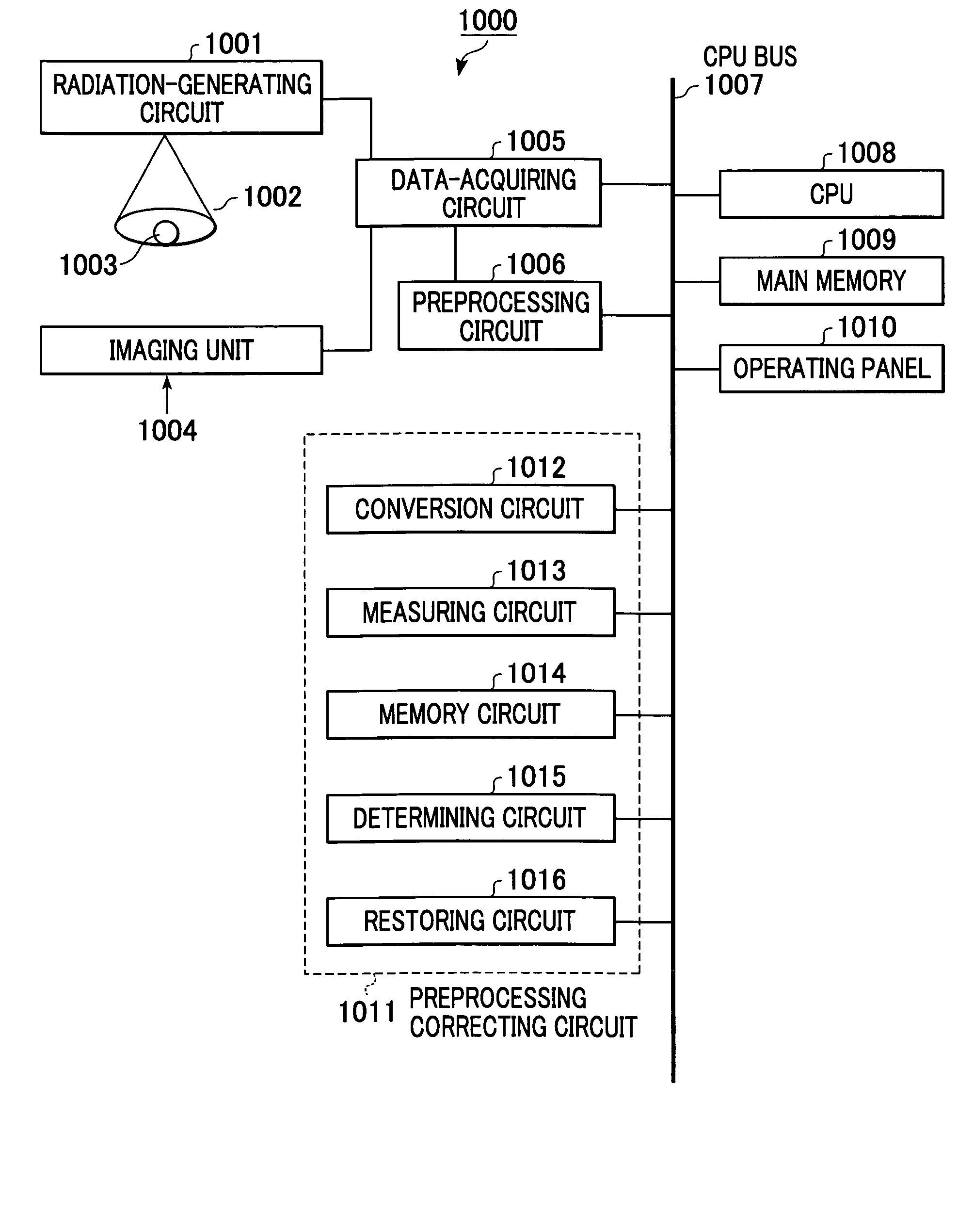
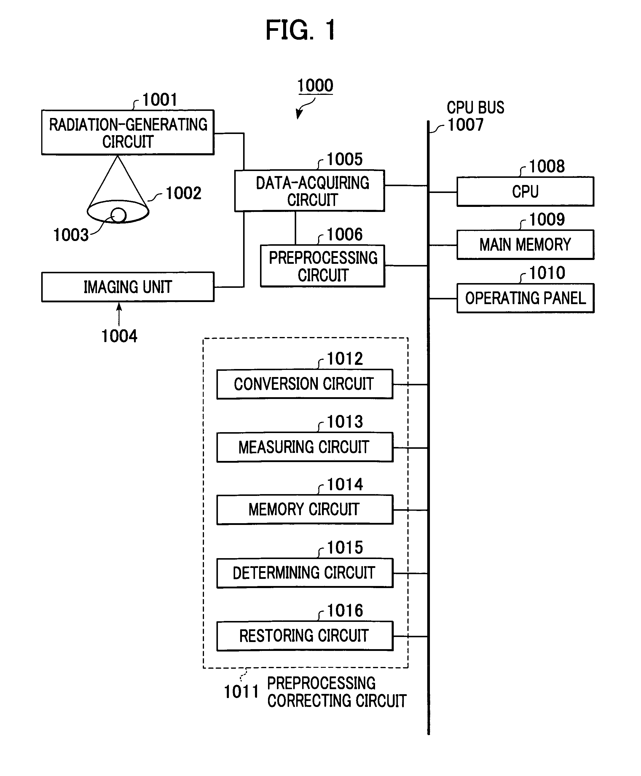
[0034] FIG. 1 shows a radiography apparatus 1000 according to the present invention. The radiography apparatus 1000 according to this embodiment has a function for objectively evaluating a change in image quality over time, particularly based on an image-quality evaluating value calculated from image data.
[0035] The radiography apparatus 1000 includes a radiation-generating circuit 1001 for emitting radiation; an imaging unit 1004 as imaging means for receiving the radiation and converting it to image data; a data-acquiring circuit 1005 for applying predetermined conversion to the image data; a preprocessing circuit 1006 for applying predetermined processing; and a preprocessing correcting circuit 1011 for calculating an image-quality evaluating value from image data and for performing restoration based on the image-quality evaluating value. The radiography apparatus 1000 further includes a CPU 1008, a main memory 1009, and an operating panel 1010. These circuits and units are contr...
second embodiment
[0074] A second embodiment will now be described with reference to FIG. 8. In the first embodiment, image-quality evaluating values are determined individually. In contrast, in the second embodiment, associated image-quality evaluating values are integrated into a comprehensive new image-quality evaluating value.
[0075] FIG. 8 is a flowchart illustrating a restoration procedure which is initiated when a change over time in relative sensitivity factor, MTF, or number of defective elements is detected, where the three indices according to the method of the present invention are taken into consideration together.
[0076] In steps S801 to S804, measurement is performed in the same manner as described above, except that a plurality of physical quantities are measured together.
[0077] Next, in step S805, a check for defective elements is performed. Then, the ratio of MTFs and the ratio of relative sensitivity factors are calculated based on image data acquired after the restoration of the def...
third embodiment
[0081] A third embodiment according to the present invention will now be described.
[0082] FIG. 9 is a flowchart for a radiography method by a radiography system according to an embodiment of the present invention.
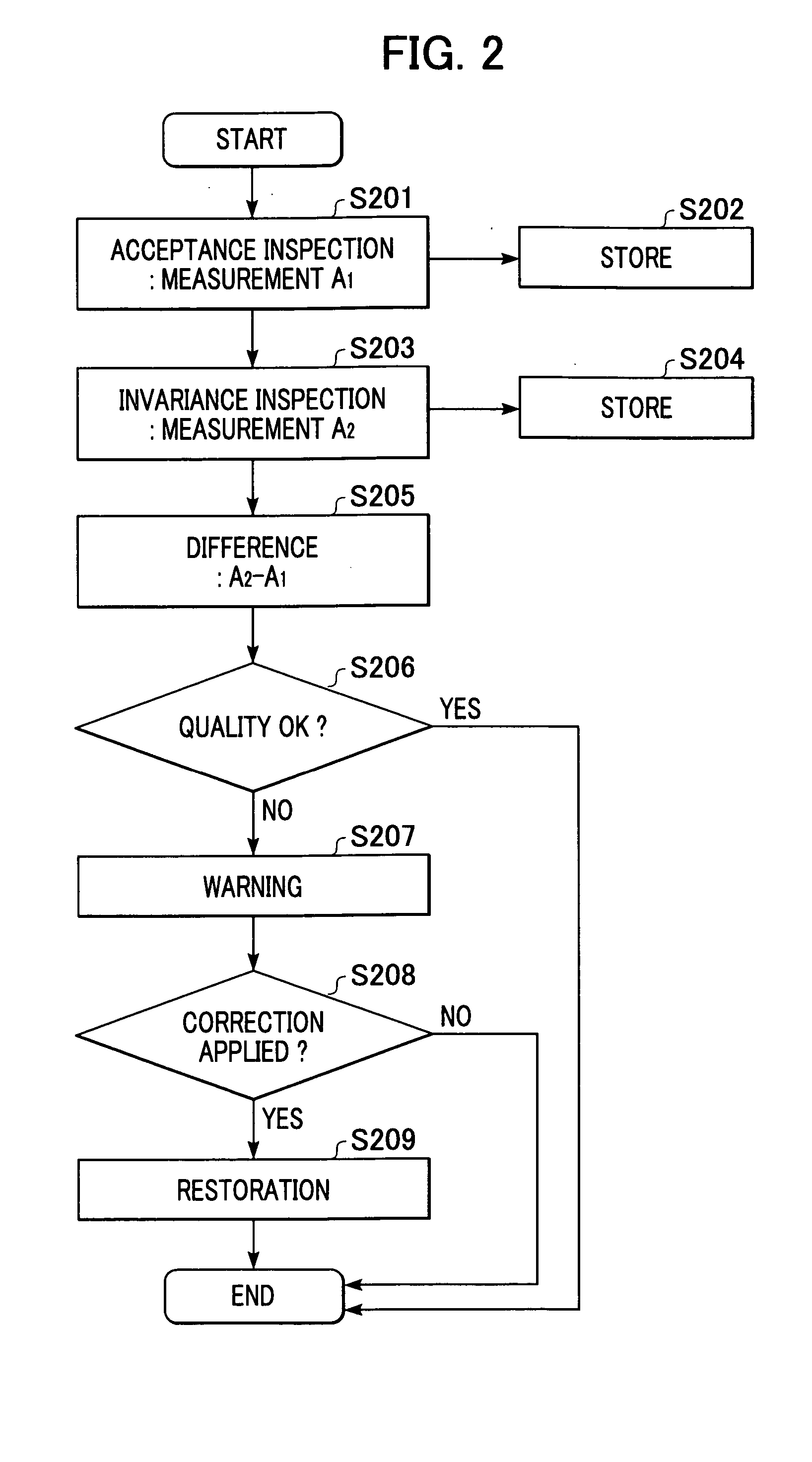
[0083] In an invariance test, the results are compared with the results of the acceptance test carried out at the time of shipment. Thus, the invariance test should be conducted with the same method as in the acceptance test. Turning to FIG. 9, in step S1101, a quality evaluation test is conducted at the time of shipment. Test items for image-quality evaluation include the sharpness, the sensitivity, etc.
[0084] The results of the image evaluation test at step S1101 are stored in step S1102 in a storage unit 28, which will be described below. The results of the image-quality evaluation test at the time of shipment are used as criteria for subsequent image-quality evaluation tests carried out for a change in image quality over time, as described below.
[0085] In step S1103, th...
PUM
| Property | Measurement | Unit |
|---|---|---|
| thickness | aaaaa | aaaaa |
| structure | aaaaa | aaaaa |
| frequency | aaaaa | aaaaa |
Abstract
Description
Claims
Application Information
 - R&D
- Intellectual Property
- Life Sciences
- Materials
- Tech Scout
- Unparalleled Data Quality
- Higher Quality Content
- 60% Fewer Hallucinations
Browse by: Latest US Patents, China's latest patents, Technical Efficacy Thesaurus, Application Domain, Technology Topic, Popular Technical Reports.
© 2025 PatSnap. All rights reserved.Legal|Privacy policy|Modern Slavery Act Transparency Statement|Sitemap|About US| Contact US: help@patsnap.com


