Downhole PV tests for bubble point pressure

a technology of bubble point pressure and downhole, which is applied in the direction of borehole/well accessories, machines/engines, instruments, etc., can solve the problems of subjective information from the bubble point pressure test and not as accurate or repeatable as desired

Inactive Publication Date: 2004-12-23
BAKER HUGHES INC
View PDF21 Cites 33 Cited by
  • Summary
  • Abstract
  • Description
  • Claims
  • Application Information

AI Technical Summary

Benefits of technology

[0011] The present invention provides an objective repeatable bubble point pressure determination method which enables new applications of downhole PV (Pressure Volume) test results such as in situ measurement of the bubble point pressure for use as a quality control parameter for sampling. The present invention provides a method and apparatus to fit data points to a curve and to smooth these points over an interval of N data points. The pressure versus volume curve is monitored to detect a transition between a gradual slope and a relatively steep slope to determine bubble point pressure by visual observation. The derivative of this smoothed curve is then analyzed to determine its peak acceleration. The peak acceleration represents the bubble point pressure. This bubble point pressure is verified by comparison to changes in fluid compressibility and visual observation of a pressure volume curve. An optimal pump rate is selected to stay above the bubble point pressure. Formation clean up and reduction of filtrate from a formation fluid or a fluid sample are determined by monitoring compressibility for the fluid or fluid sample.

Problems solved by technology

This problem is particularly important for deepwater exploration.
If a non-representative sample is used to determine fluid properties, then during production asphaltenes may unexpectedly come out of solution near the wellbore or in the marine riser or the production pipelines.
The capability to perform the downhole bubble point test was introduced some time ago in Michaels, J., Moody, M., and Shwe, T.: "Advances in Wireline Formation Testing," paper presented at the 1995 SPWLA Annual Logging Symposium, Paris, France, Jun. 26-29, 1995, but in practice, information from the bubble point pressure test is subjective and not as accurate or repeatable as desired.

Method used


Image

  • Downhole PV tests for bubble point pressure
  • Downhole PV tests for bubble point pressure
  • Downhole PV tests for bubble point pressure

Examples


Embodiment Construction

[0026] The following nomenclature is used in the following detailed description:

[0027] k Permeability, L.sup.-2.

[0028] P Pressure, (pounds per square inch (psi). (M / LT.sup.2)

[0029] q Volumetric flow rate, L.sup.3 / T.

[0030] r Radius, cm.

[0031] G.sub.o Geometric factor, 1 / L.

[0032] c.sub.t Compressibility, (M / LT.sup.2).sup.-1

[0033] V.sub.sys Volume of tool system, L.sup.3.

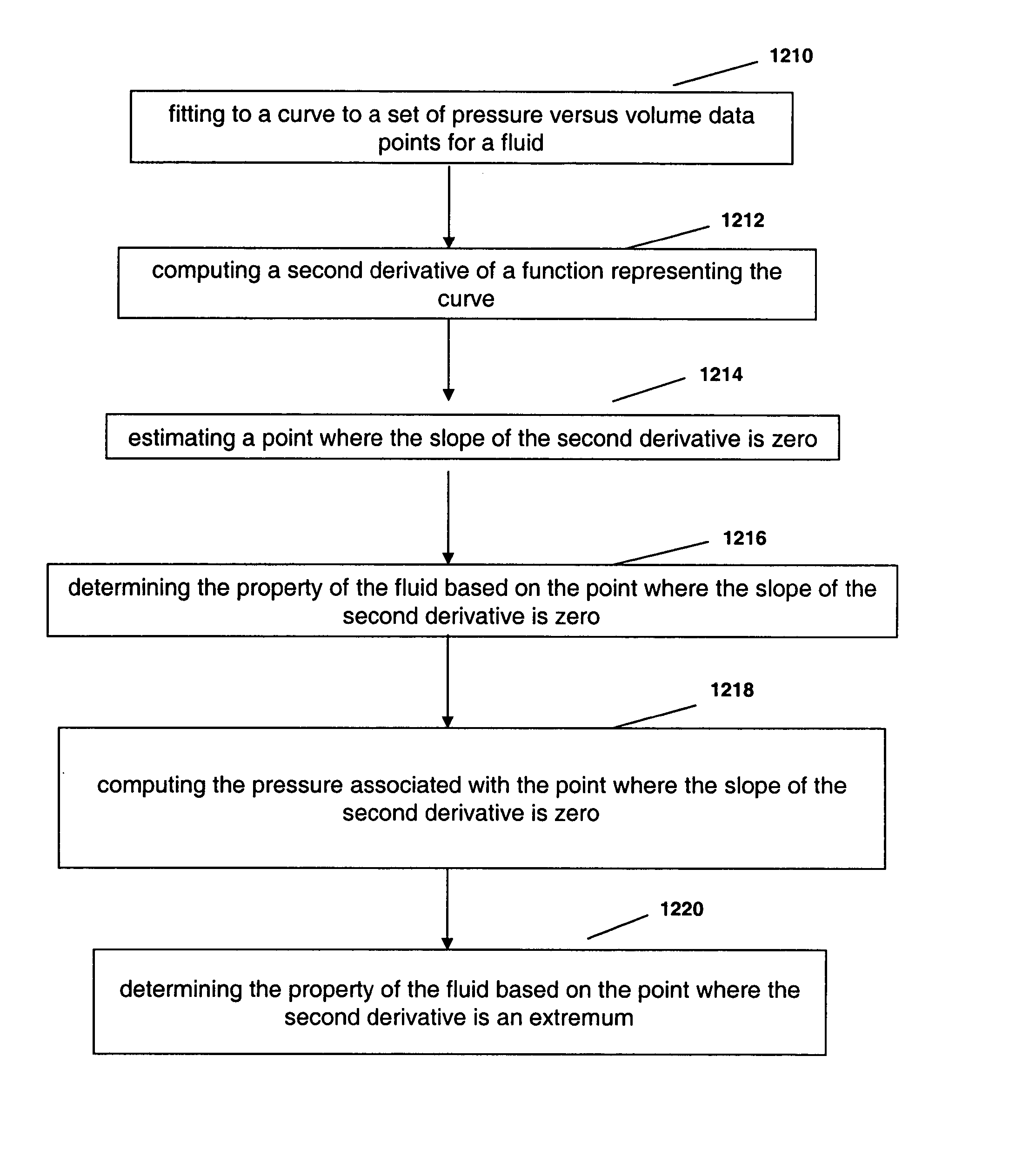
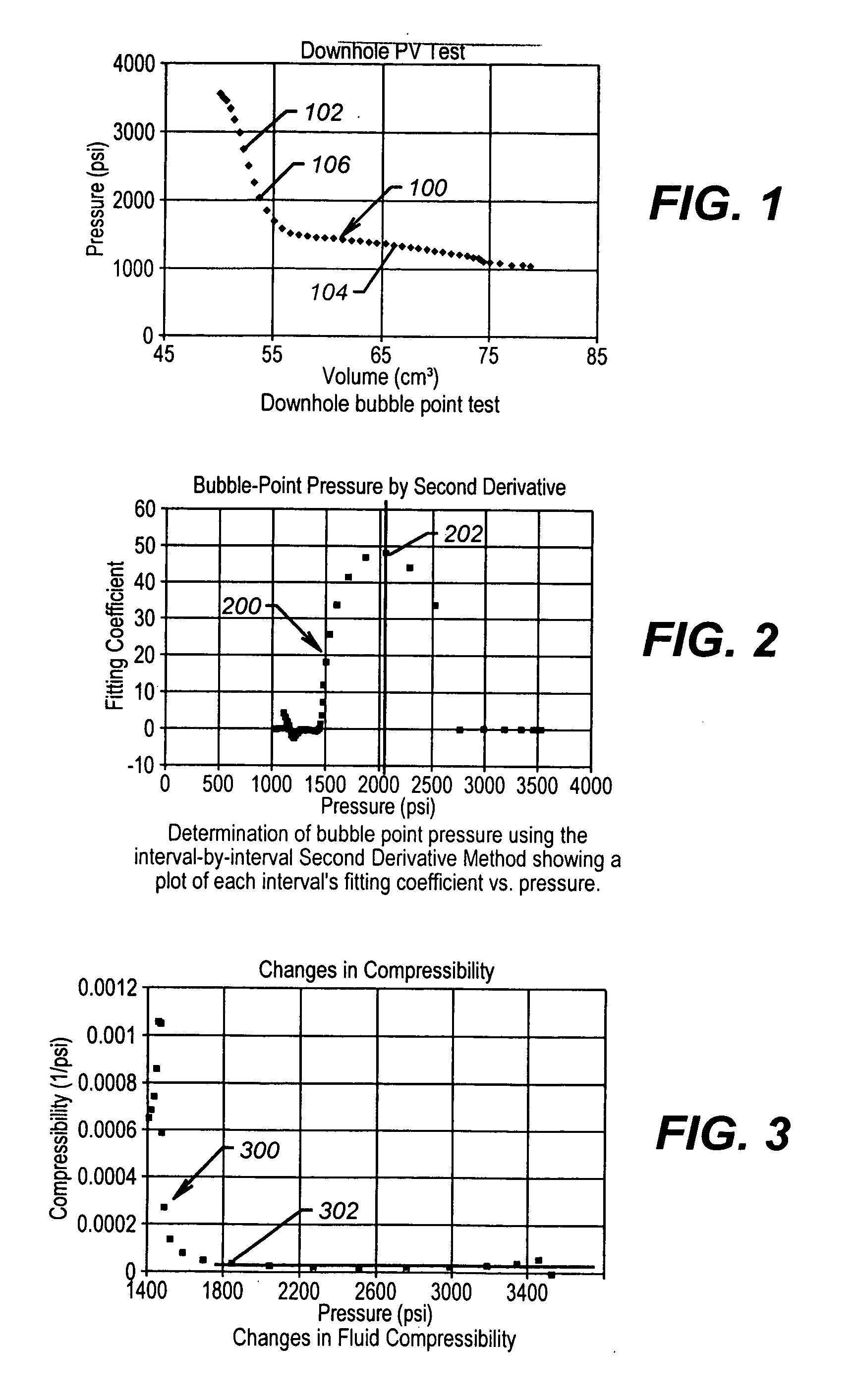
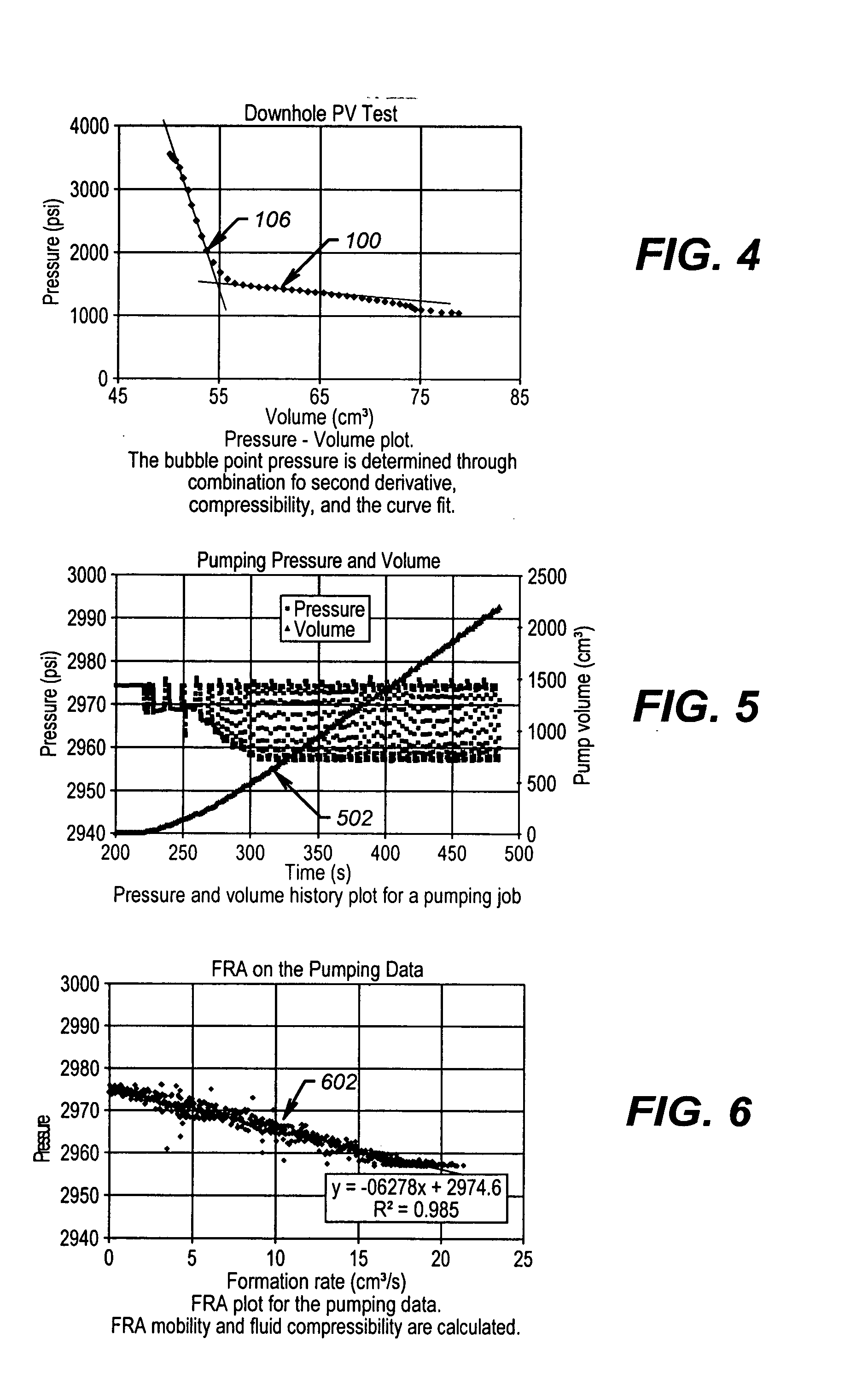
[0034] Turning now to FIG. 1, the shape of a pressure versus volume plot 100 is a steeply sloping line 102, followed by a gently sloping line 104. The bubble point pressure is the pressure at which the steeply sloping line first curves upward 106.

[0035] Traditionally bubble point has been estimated from such curves visually. Visual interpretation is by nature subjective, rather than objective and thus necessarily variant and difficult to produce repeatable results between wells or samples taken in the same well. The present invention provides a novel automated method and apparatus, providing an objection which removes ...


PUM

PropertyMeasurementUnit
pressureaaaaaaaaaa
pressureaaaaaaaaaa
point pressureaaaaaaaaaa

Abstract

The present invention provides an objective bubble point pressure determination method enables new applications of downhole PV (Pressure Volume) test results such as in situ measurement of the bubble point pressure for use as a quality control parameter for sampling. The present invention provides a method and apparatus to fit data points to a curve and to smooth these points over an interval of N points. The derivative of the curve is determined to obtain peak acceleration. The peak acceleration represents the bubble point pressure. This bubble point pressure is verified by comparison to changes in fluid compressibility and visual observation of a pressure volume plot history.

Description

[0001] This patent application claims priority from U.S. patent application No. 60 / 480,149 filed on Jun. 20, 2003 entitled "Improved Downhole PV Tests for Bubble Point Pressure" by Rocco DiFoggio, Jaedong Lee and John Michaels.[0002] 1. Field of the Invention[0003] The present invention relates to the field of downhole formation fluid sampling and in particular to the determination of bubble point pressure for a fluid down hole.[0004] 2. Background of the Related Art[0005] A primary function of a wireline formation fluid sampling and testing tool, such as the Reservoir Characterization Instrument (RCI.TM.) provided by Baker Atlas, is to collect multiple reservoir fluid samples to evaluate potentially productive reservoir units.[0006] These collected fluid samples are brought to an onshore laboratory facility for PVT (Pressure, Volume, Temperature) and compositional analysis. It is important to obtain high quality samples, which can be used with confidence to predict reservoir behavi...

Claims


Application Information

Patent Timeline
Patent Type & Authority Applications(United States)
IPC IPC(8): G01N7/00G01N9/28G01N13/02G01N33/28
CPCG01N7/00G01N9/28G01N33/2823G01N2013/0266
Inventor DIFOGGIO, ROCCOMICHAELS, JOHN M.LEE, JAEDONG
Owner BAKER HUGHES INC
Why Eureka
Try Eureka