
System and method for scenario generation in a distributed system

a distributed system and scenario technology, applied in the field of distributed computer systems, can solve the problems of large manpower resources, difficult to test such a system for reliability, and manual tests that are not nearly exhaustive,

Active Publication Date: 2004-12-23
ORACLE INT CORP
View PDF25 Cites 37 Cited by
  • Summary
  • Abstract
  • Description
  • Claims
  • Application Information

AI Technical Summary

Benefits of technology

"The invention is a system and method for testing distributed computer systems, which involves emulating scenarios to test their reliability. The system includes nodes and agents that communicate with each other through a network, and a central controller that manages the system. The agents receive instructions from the central controller and implement them by interacting with the system's resources. The system can be tested by running various scenarios, and the results can be analyzed using a central controller. The invention helps to automate the testing process and ensures that scenarios are tested exhaustively."

Problems solved by technology

Because of the large number of possible system configurations described above, testing such a system for reliability may prove difficult.
Certain common scenarios may be covered by manual testing, but such manual tests may not be nearly exhaustive, and require extensive manpower resources.
Alternatively, automated testing and scripting methods may be used to expand the footprint of coverage, but these methods also have limits.
In addition, scripts may not be applicable across different operating systems.
Furthermore, scripting for each resource may not allow for extensive interaction between resources, and may lack a central point of control and analysis.
For example, a UNIX shell script running on one node may not be able to control the operation of another node.
Because a distributed system may be useful precisely because it allows the interaction of scattered heterogeneous resources to be directed from a central location, this may represent a limitation in any such testing strategy.

Method used


Image

  • System and method for scenario generation in a distributed system
  • System and method for scenario generation in a distributed system
  • System and method for scenario generation in a distributed system

Examples


Embodiment Construction

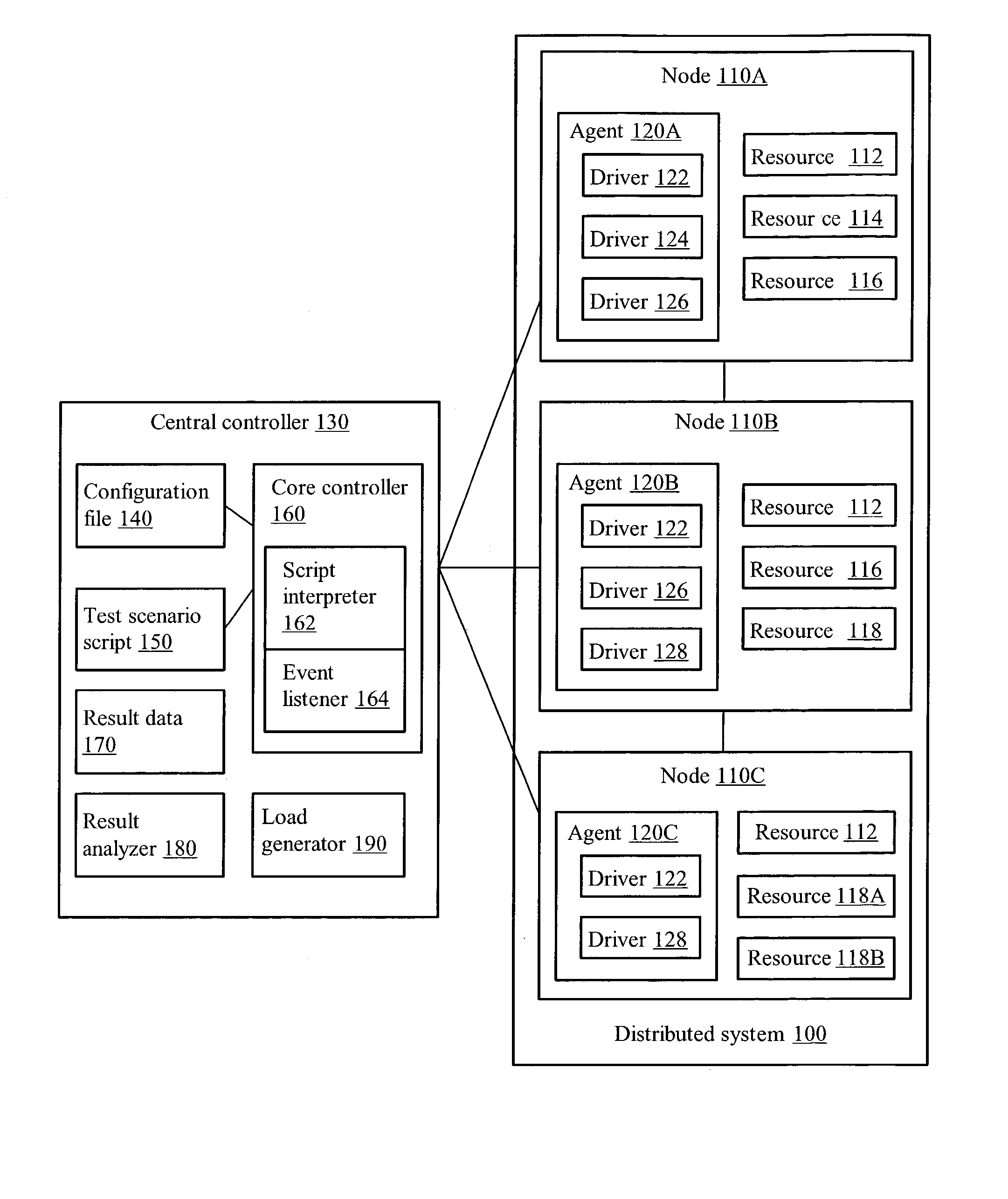
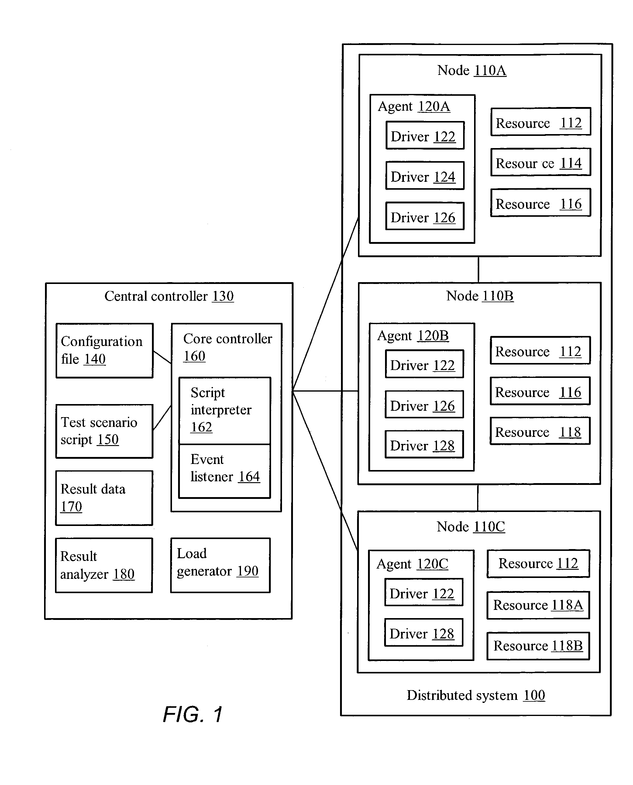
[0017] Turning now to FIG. 1, an exemplary distributed system 100 is shown along with a central controller 130, according to one embodiment. Distributed system 100 includes nodes 110A-C, each of which further includes a corresponding agent 120A-C. Central controller 130 may include configuration file 140, test scenario script 150, and core controller 160, as well as result data 170, result analyzer 180, and load generator 190. Nodes 110A-C communicate to central controller 130 by some form of interconnect, which may be a system backplane, a local area network (LAN), a wide area network (WAN), the Internet, or some combination thereof.

[0018] Each node 110A-C may represent a computer system operable to perform one or more of a variety of functions within the distributed system 100. Such functions may include, but are not limited to, acting as a database, web server, directory server, application server, or e-commerce server. In addition, each node 110A-C in FIG. 1 may represent a clus...


PUM


Abstract

A system and method may emulate scenarios for testing a distributed system. The distributed system may include a plurality of nodes, each having one or more resources. The system may include a resource driver for each type of the one or more resources in the distributed system, as well as one or more agents configured to access each resource through the corresponding resource driver. At least one node in the distributed system may be configured to run on a different platform than another node in the distributed system. The system may further include a central controller configured to communicate with each agent. The central controller may further execute a test scenario script containing one or more test scenarios for the distributed system.

Description

[0001] 1. Field of the Invention[0002] This invention relates to the field of distributed computer systems and, more particularly, to testing heterogeneous distributed systems.[0003] 2. Description of the Related Art[0004] As workloads on modern computer systems become larger and more varied, more and more computational resources are needed. For example, a request from a client to web site may involve one or more load balancers, web servers, databases, application servers, etc. Alternatively, some large-scale scientific computations may require multiple computational nodes operating in synchronization as a kind of parallel computing.[0005] Any such collection of resources tied together by a data network may be referred to as a distributed system. A distributed system may be a set of identical or non-identical nodes connected together by a local area network. Alternatively, the nodes may be geographically scattered and connected by the Internet, or a heterogeneous mix of computers, e...

Claims


Application Information

Patent Timeline
Patent Type & Authority Applications(United States)
IPC IPC(8): G06F11/00G06F11/273
CPCG06F11/2294G06F11/3664G06F11/3688
Inventor BHOWMIK, SUSHRUTSUMAR, SHUBHANKAR
Owner ORACLE INT CORP
Learn More