Evaporative emission control system
a technology of evaporative emission control and control system, which is applied in the direction of electric control, ignition automatic control, combustion-air/fuel-air treatment, etc., can solve the problems of high fuel concentration of purge gas flowing from the canister, and the inability to maintain the appropriate air/fuel ratio control
- Summary
- Abstract
- Description
- Claims
- Application Information
AI Technical Summary
Benefits of technology
Problems solved by technology
Method used
Image


Examples
first embodiment
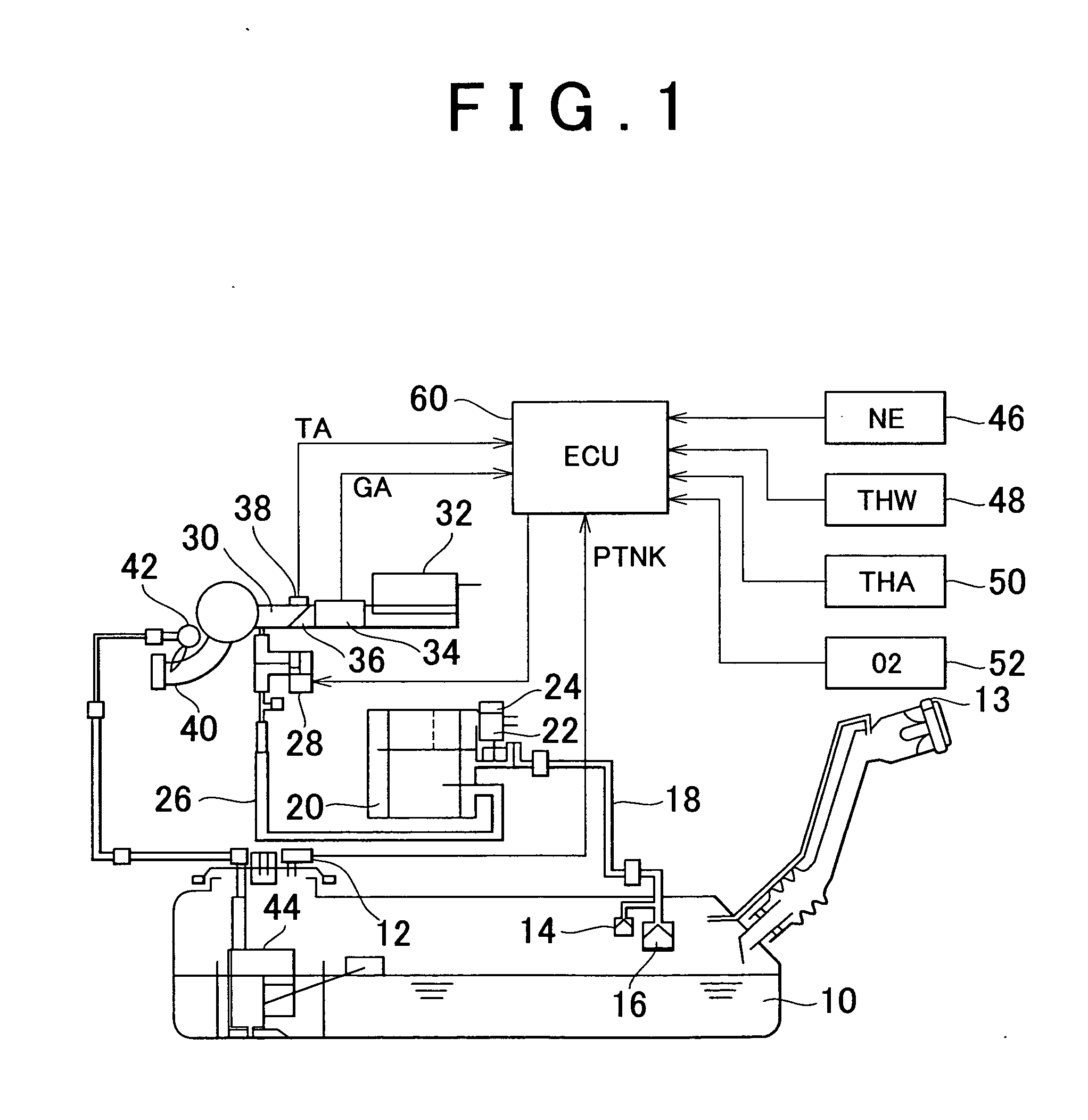
[0062] FIG. 1 shows the construction of an evaporative emission control system according to the first embodiment of the invention. The evaporative emission control system of this embodiment includes a fuel tank 10. The fuel tank 10 is provided with a tank pressure sensor 12 for measuring the pressure (tank pressure) PTNK in the fuel tank 10. A filler cap for closing a filler opening of the fuel tank 10 is provided with a check valve 13 that only allows flow of gas from the outside of the fuel tank 10 to the inside thereof. To the fuel tank 10 is connected one end of a vapor conduit 18 via roll over valves (ROV) 14, 16.
[0063] The other end of the vapor conduit 18 is connected to a canister 20. The canister 20 contains activated carbon, which adsorbs fuel vapors flowing from the fuel tank 10 through the vapor conduit 18. The canister 20 has an atmospheric vent in which a canister closed valve (CCV) 22 and a check valve 24 are disposed. The CCV 22 is a normally closed solenoid-operated...
second embodiment
[0114] Referring next to FIG. 5, the second embodiment of the invention will be described. The system of this embodiment is similar in construction to that of the first embodiment, and is characterized in that the ECU 60 executes a control routine shown in FIG. 5 as described later, in addition to or in place of the above-described routine shown in FIG. 4.
[0115] When the accelerator pedal is released and the engine speed NE is sufficiently high, fuel cut (F / C) control is performed in which fuel injection in the engine is stopped. When the canister 20 is to be purged of fuel vapor, the ECU 60 checks if the fuel cut (F / C) control is being executed, and drives the purge VSV 28 at a suitable duty ratio as long as the fuel cut (F / C) control is not performed. Accordingly, when the purge VSV 28 is normal, no purge gas flows in the system during execution of the fuel cut (F / C) control, thus avoiding a situation where only the fuel contained in the purge gas is supplied into each cylinder of...
third embodiment
[0125] Referring next to FIG. 6 and FIG. 7, the third embodiment of the invention will be described. The system of this embodiment is similar in construction to that of the first or second embodiment, and is characterized in that the ECU 60 executes a routine shown in FIG. 7 as described later, in place of the process of step S132 of FIG. 3.
[0126] In the present embodiment, too, the ECU 60 calculates the fuel injection time TAU according to the above-indicated expression (2): TAU=TP.times.(FW+FAF+KGX+FPG). The water temperature factor FW included in this expression is a factor for increasing the amount of fuel upon a cold start of the engine so as to stabilize the operating state of the engine. FIG. 6 is a map showing one example of the relationship between the water temperature factor FW and the coolant temperature THW. As shown in FIG. 6, FW is set as a function of the coolant temperature THW, and is made equal to zero in a range (e.g., a range of THW.gtoreq.70.degree. C.) in whic...
PUM
 Abstract
Description
Claims
Application Information