
Methods and system for determining engine air-fuel ratio imbalance

一种发动机、操作方法的技术,应用在发动机元件、燃烧发动机、发动机点火等方向,能够解决气缸空燃比不平衡等问题,达到减少排放物的效果

Pending Publication Date: 2020-06-19
FORD GLOBAL TECH LLC
View PDF0 Cites 0 Cited by
  • Summary
  • Abstract
  • Description
  • Claims
  • Application Information

AI Technical Summary

Problems solved by technology

However, for engines that include multiple cylinders with only one pre-catalyst oxygen sensor per cylinder, it may be difficult to determine individual cylinder air-fuel ratio imbalances because a single oxygen sensor may be exposed to exhaust gas from all cylinders in the bank

Method used


Image

  • Methods and system for determining engine air-fuel ratio imbalance
  • Methods and system for determining engine air-fuel ratio imbalance
  • Methods and system for determining engine air-fuel ratio imbalance

Examples


Embodiment Construction

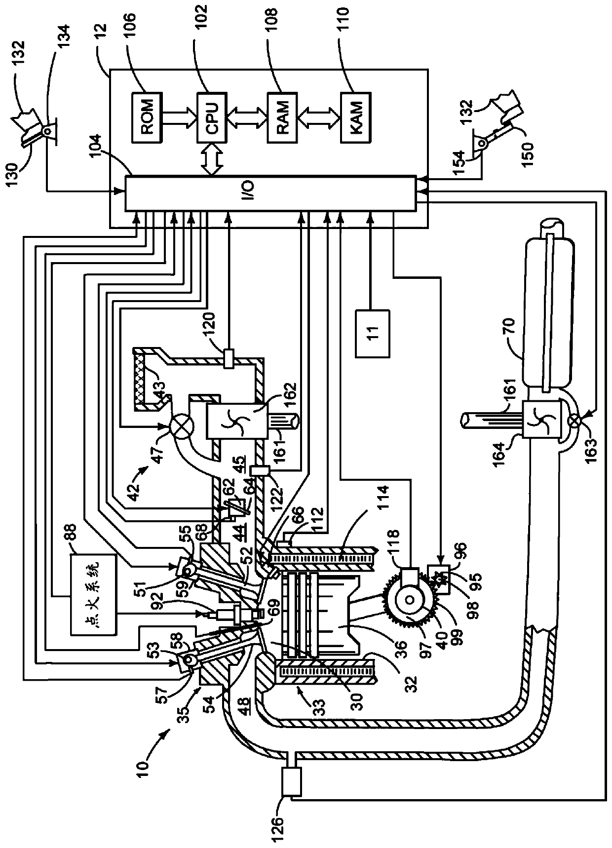
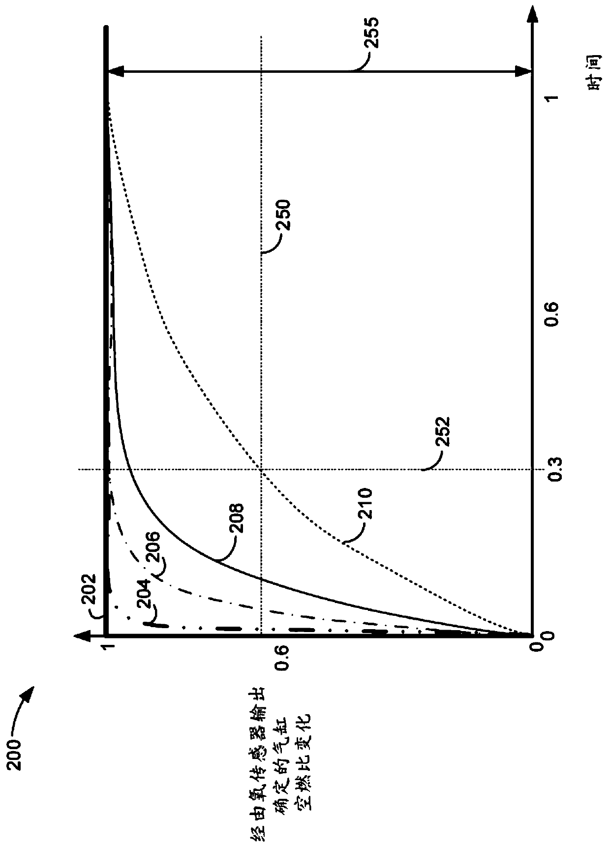
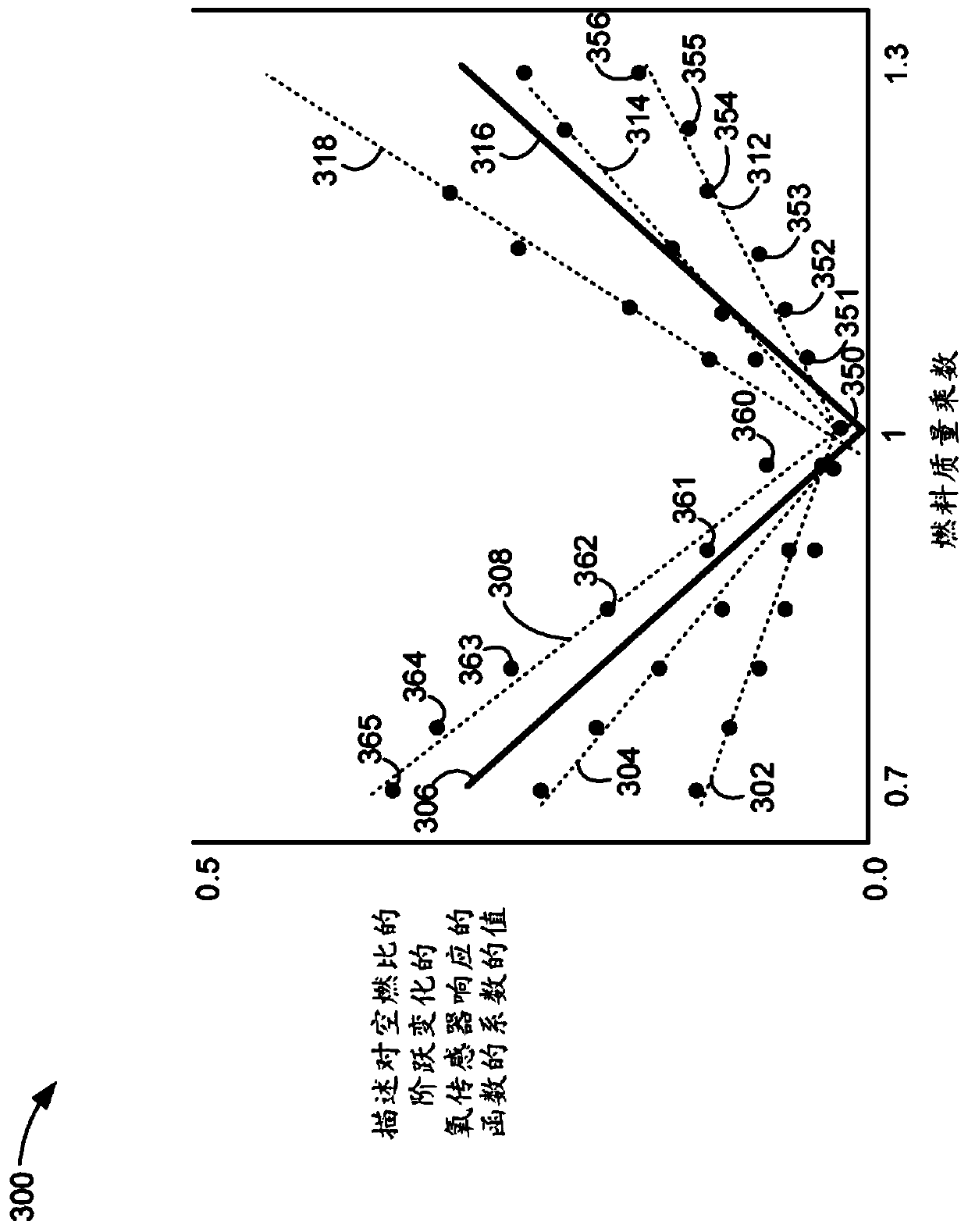
[0014] This instruction relates to operating a vehicle's internal combustion engine. engine can be figure 1 type shown. Engines may be operated with conditions between one or more cylinders that may result in increased engine emissions. Imbalance can be detected via a step change in the air-fuel ratio input to the engine cylinders, as in figure 2 shown. The oxygen sensor output in response to a step input in air-fuel ratio or lambda can be applied to generate a straight line showing the relationship between the coefficients of the function and the air-fuel ratio multiplier, as image 3 shown. One or more lines can be the basis for determining the cylinder air-fuel ratio imbalance, such as Figure 4 depicted. exist Figure 5 and Figure 6 A method for determining and compensating for an air-fuel ratio imbalance in an engine cylinder is shown in the method of .

[0015] refer to figure 1 , an internal combustion engine 10 comprising one or more cylinders is controlled...


PUM


Abstract

The invention provides a methods and system for determining engine air-fuel ratio imbalance. Systems and methods for operating an engine that includes an oxygen sensor and one or more fuel injectors for each engine cylinder are described. In one example, lines describing a relationship between a fuel mass multiplier and a coefficient of a function describing output of an oxygen sensor to a step change in fuel mass are a basis for determining air-fuel imbalance of engine cylinders.

Description

technical field [0001] The present description relates to methods and systems for determining and compensating for engine cylinder air-fuel ratio imbalances. Background technique [0002] An internal combustion engine may include a number of cylinders in which combustion occurs. Each of the plurality of cylinders may receive fuel from a dedicated fuel injector. Additionally, each of the plurality of cylinders may receive air from a dedicated intake passage. Manufacturing deviations, wear, and dimensional differences in the intake passages of engine cylinders can cause air-fuel imbalances in the cylinders. The air-fuel imbalance within the cylinders can cause variations in the exhaust gases leaving the engine cylinders and entering catalysts in the engine's exhaust system. Changes in exhaust gas entering the catalyst can reduce catalyst efficiency and increase exhaust emissions. However, for engines that include multiple cylinders with only one pre-catalyst oxygen sensor ...

Claims


Application Information

Patent Timeline
Patent Type & Authority Applications(China)
IPC IPC(8): F02D41/30F02P5/15F02D37/02
CPCF02D37/02F02D41/0085F02D41/30F02P5/1512F02D41/0002F02D41/1401F02D41/1454F02D41/1475F02D41/2422F02D41/2454F02D2041/1433F02D2200/0404F02D2200/0614F02D2200/602Y02T10/40F01N2560/025F02D41/1441
Inventor 迈克尔·克鲁兹纳罗伯特·詹特斯肯尼士·约翰·贝尔克里斯多夫·韦伯安德鲁·巴尼亚斯科
Owner FORD GLOBAL TECH LLC
Learn More