Method for controlling air-fuel ratio for an alternating valve engine

A technology of air-fuel ratio and internal combustion engine, which is applied in the direction of engine components, combustion engine, engine control, etc., to achieve the effects of improving emissions, consistent cylinder torque, and saving energy

Inactive Publication Date: 2009-04-15
FORD GLOBAL TECH LLC
View PDF3 Cites 0 Cited by
  • Summary
  • Abstract
  • Description
  • Claims
  • Application Information

AI Technical Summary

Problems solved by technology

[0003] The methods mentioned above can also have some disadvantages

Method used


Image

  • Method for controlling air-fuel ratio for an alternating valve engine
  • Method for controlling air-fuel ratio for an alternating valve engine
  • Method for controlling air-fuel ratio for an alternating valve engine

Examples


Embodiment Construction

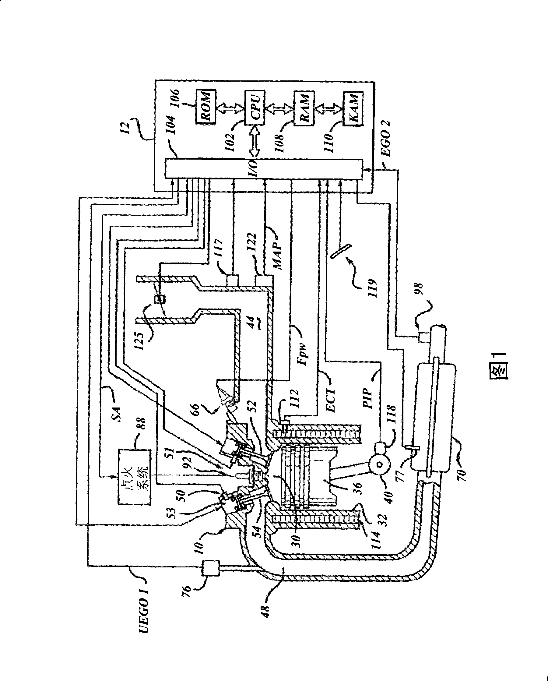
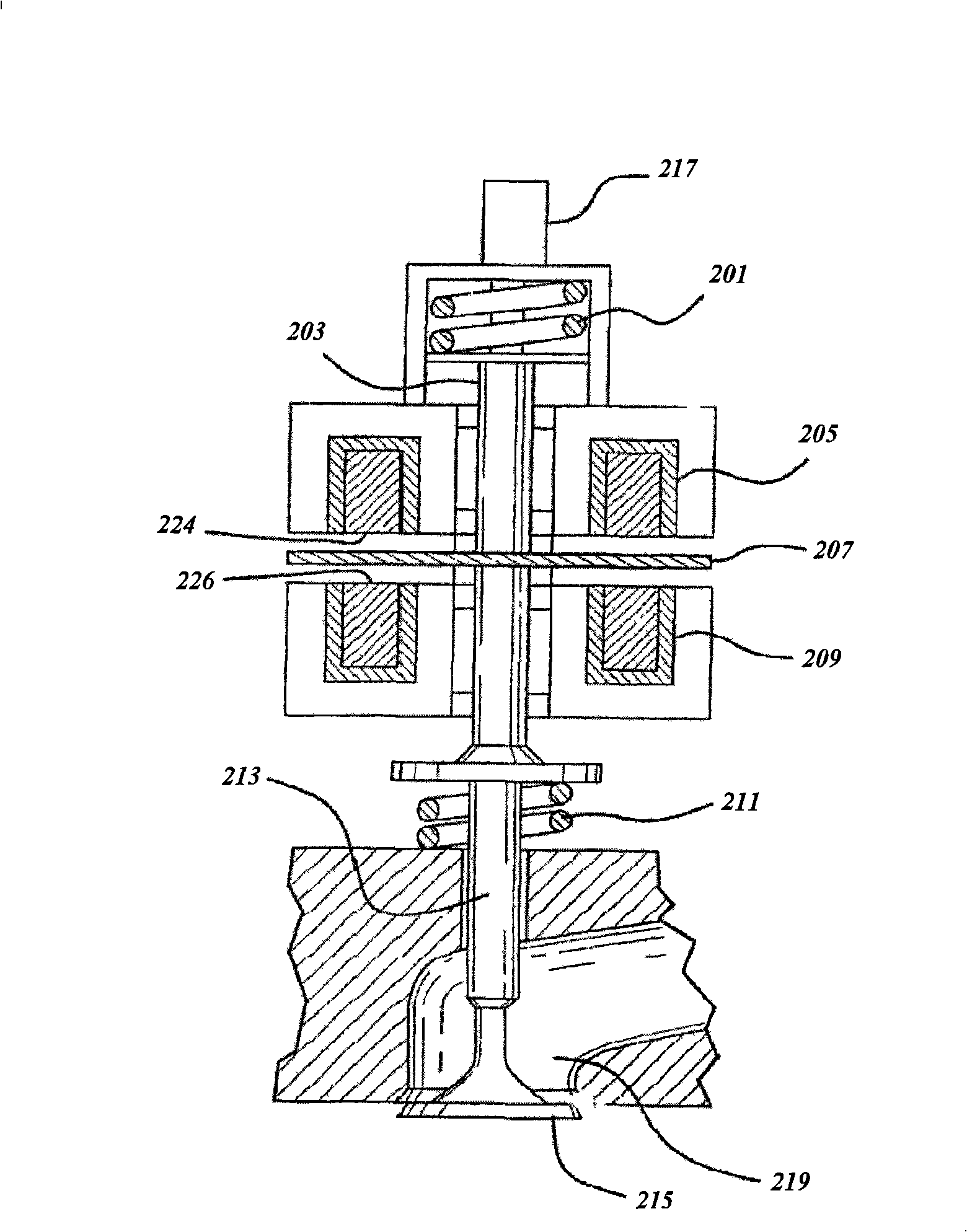
[0017] Referring to FIG. 1 , an internal combustion engine 10 including a plurality of cylinders (one of which is shown in FIG. 1 ) is controlled by an electronic engine controller 12 . Engine 10 includes combustion chamber 30 and cylinder walls 32 with piston 36 positioned within and connected to crankshaft 40 . Combustion chamber 30 is shown communicating with intake manifold 44 and exhaust manifold 48 via respective intake valve 52 and exhaust valve 54 . Each intake valve 52 and exhaust valve 54 may be operated by electromechanically controlling a valve coil and armature assembly 53 . Alternatively, intake valve 52 or exhaust valve 54 may be mechanically actuated. The armature temperature is determined by a temperature sensor 51 . Valve position is determined by position sensor 50 . Valve position can be determined by linear adjustable displacement, discrete or optical sensors, or from actuator current measurements. In an alternative example, each valve actuator for val...


PUM


Abstract

A method for controlling the air-fuel ratio of an internal combustion engine operating with alternating intake valves is presented, comprising: operating at least one cylinder of the internal combustion engine with a first inlet port and a second inlet port; operating the first inlet port and the second inlet port in the during an alternating cylinder cycle; and adjusting the timing of the first inlet port or the second inlet port in response to the air intake of the cylinder sucked into the cylinder, wherein the air intake of the cylinder is sucked during the cylinder cycle of the cylinder, and the cylinder circulation generates before the adjusted timing is used for the cylinder. According to the method, the air-fuel ratio of the internal combustion engine is adjusted through changing valve timing or fuel timing during the cylinder cycle. The inventive method reduces discharge of the engine.

Description

【Technical field】 [0001] The present invention relates to a method for improving the air-fuel ratio control of an internal combustion engine operating with alternating intake valve timing. 【Background technique】 [0002] A method for stochastically operating operable valves in an internal combustion engine is described in US Patent Publication No. 7,066,121. This method describes the different cylinder cycles of a cylinder (a cylinder cycle is defined here as the duration of the crankshaft angle during which a cylinder is repeatedly operated, e.g. a cylinder cycle of a four-stroke cylinder cycle is 720 crankshaft angles, but should Note that depending on the number of strokes per cylinder cycle, the cylinder's two intake valves may be alternately actuated or opened during that cylinder cycle). That is, during one cylinder cycle, the first of the two intake valves remains closed while the second intake valve remains open. Subsequently, the second intake valve remains closed...

Claims


Application Information

Patent Timeline
Patent Type & Authority Applications(China)
IPC IPC(8): F02B15/00F01L9/20
CPCF02D41/1473Y02T10/42Y02T10/18F02D2041/001F01L9/04F02D13/0234F02D41/18F02D41/0002Y02T10/12Y02T10/40F01L9/20
Inventor 亚历山大·奥康诺·吉布森伊尔亚·弗拉迪米尔·科尔马纳弗斯凯约翰·奥塔维奥·米歇里尼宋刚
Owner FORD GLOBAL TECH LLC
Why Eureka
Try Eureka