
Device for splitting a two-phase stream into two or more streams with the desired vapor/liquid ratios

a two-phase stream and vapor/liquid technology, which is applied in the direction of branching pipes, gas/liquid distribution and storage, water supply tanks, etc., can solve the problems of not always being able to stay inside the desired “dispersed flow regime, the two-phase stream cannot be split symmetrically into the outlet stream, and the vapor/liquid ratio is not always equal, so as to achieve cost-effective, simple and robust design, and low maintenance

Active Publication Date: 2005-01-06
MORTEN MULLER LTD APS
View PDF18 Cites 49 Cited by
  • Summary
  • Abstract
  • Description
  • Claims
  • Application Information

AI Technical Summary

Benefits of technology

This new type of splitter has several technical benefits compared to previous designs. Firstly, it allows for more precise control over the amount of liquid being output from each stream. Secondly,it works effectively regardless of changes in fluid properties or other factors such as temperature or pressure. Thirdly,the splitter operates without causing blockages or leaks, making it easier to install and maintain. Fourthly,the splitter produces consistent results even when used with various types of piping configurations. Fifthly,the splitter does not require expensive or complicated instruments or controls. Lastly,the splitter provides better safety standards due to its lack of sensitivity to external influences. Overall, this new design offers improved efficiency, reliability, and flexibility while keeping costs low.

Problems solved by technology

The technical problem addressed in this patent is how to improve the accuracy and reliability of separating liquids and gases in devices used in industry without increasing their complexity and cost. Current methods often involve multiple components and have limitations when trying to achieve optimal control.

Method used


Image

  • Device for splitting a two-phase stream into two or more streams with the desired vapor/liquid ratios
  • Device for splitting a two-phase stream into two or more streams with the desired vapor/liquid ratios
  • Device for splitting a two-phase stream into two or more streams with the desired vapor/liquid ratios

Examples


Embodiment Construction

Splitting a two-phase stream into two or more outlet streams with identical vapor-to-liquid ratios in each outlet stream is needed upstream of many types of industrial process equipment. Examples are: In process furnaces, parallel furnace tubes are most often used for the process fluid in order to avoid excessive furnace tube diameter and to allow for an economical furnace design. Therefore, the feed stream needs to be split to the parallel furnace tubes upstream from the furnace. In modern process plants, parallel trains of heat exchangers, such as trains of shell and tube heat exchangers are often used. This is either to avoid excessive tube bundle diameters and / or to optimize the heat integration in the process plant. Air cooler bundles are most often arranged in parallel due to the limitations in bundle size and due to the poor distribution of fluids to the parallel air cooler tubes in case of excessive inlet header length. Chemical reactors, such as trickle bed reactors, m...


PUM

PropertyMeasurementUnit
Distanceaaaaaaaaaa
Distanceaaaaaaaaaa
Flow rateaaaaaaaaaa

Abstract

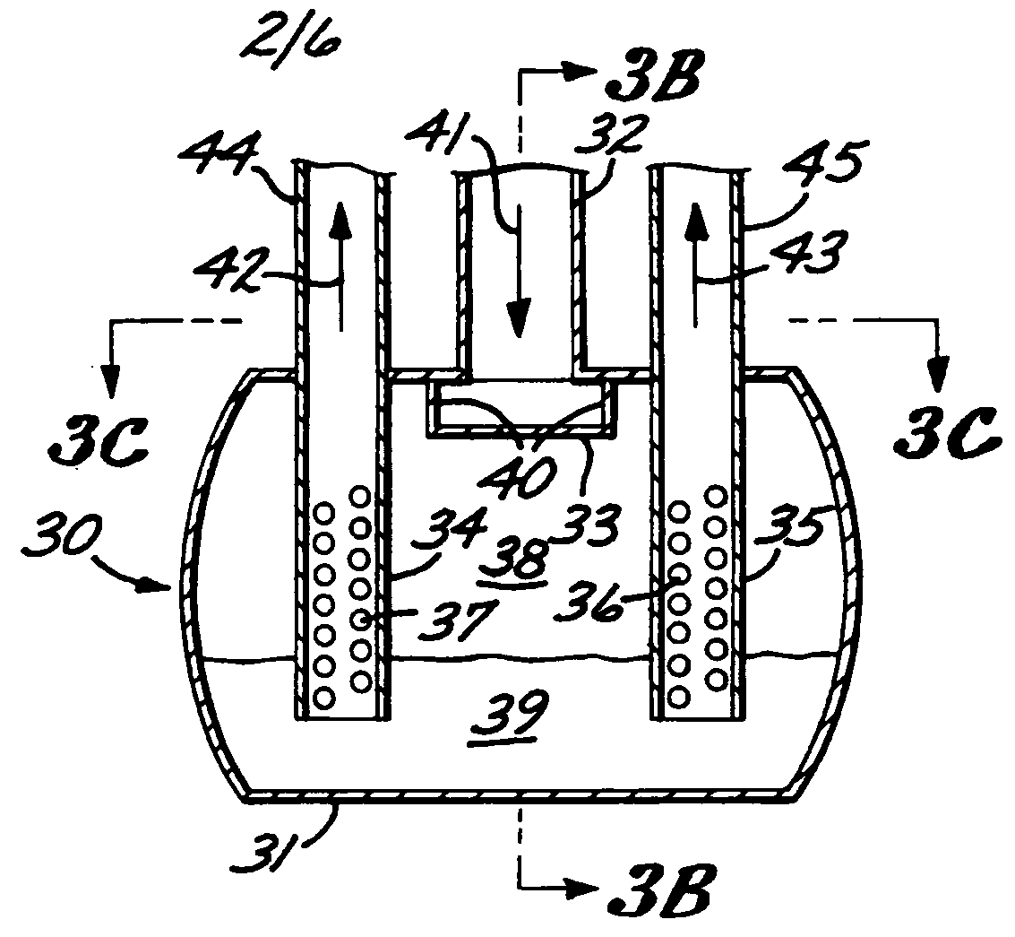
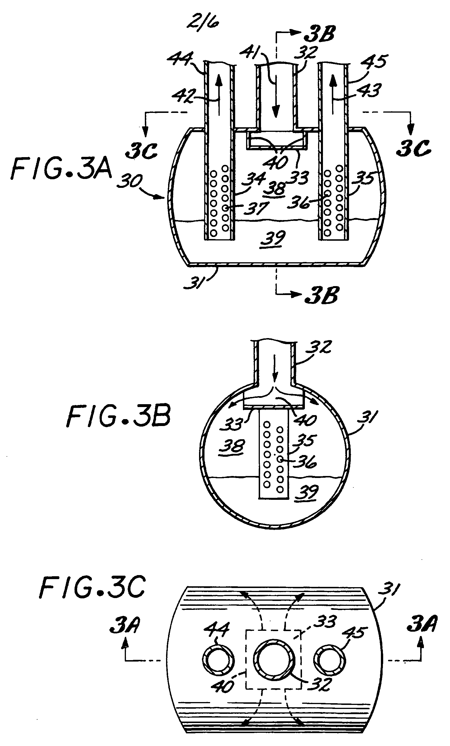
A stream splitting device splits a two-phase inlet stream into two or more outlet streams having nearly identical vapor-to-liquid ratios. The inlet stream is directed into a separator vessel containing an impingement plate to decrease the velocity of the stream and direct it toward the inner walls of the vessel, where it impinges, separating the liquid from the vapor. Inside the vessel, each of two vertical suction channels with side wall apertures is in fluid communication with an outlet pipe. The lower ends of the suction channels are submerged in the liquid phase. Vapor flows though the apertures that are above the liquid surface in the vessel, thereby generating a pressure drop across the walls of the suction channels. Consequently, liquid is lifted up into the suction channels, where it is mixed with the vapor. The two-phase mixture then leaves the vessel and stream splitter through the outlet pipes.

Description


Claims


Application Information

Patent Timeline
Owner MORTEN MULLER LTD APS
Learn More