Basket frame

a basket frame and basket body technology, applied in the field of basket frames, can solve the problems of inconvenient use for users of the conventional basket frame for installing various accessories, and achieve the effects of convenient use, quick assembly, and widening of the basket fram

Inactive Publication Date: 2005-01-06
ULIKE
View PDF16 Cites 15 Cited by
  • Summary
  • Abstract
  • Description
  • Claims
  • Application Information

AI Technical Summary

Benefits of technology

[0006] It is therefore the main object of this invention to provide a basket frame which can be assembled quickly and equipped with various accessories and can be changed in its width. The basket frame is composed of a left side frame, a right side frame, a front side frame, a back side frame and four joints, the left side frame and the right side frame having respectively a leading groove which can be slid on a sliding rail to be drew out from or pushed into the cabinet. The front side frame and the back side frame have respectively a fitting groove, at least one or more pairs of supporting seats can be installed opposite in the fitting groove of the front side frame and the back side frame for supporting hanging rod or hanging basket, further, the four side frames can be assembled to connect with each other quickly by the four joints.
[0007] It is another object of this invention to provide a basket frame which can be assembled quickly by means of joints, the joint being formed into L-shape, one end of the joint having two inserting blocks which can be inserted into one end of the left side frame or the right side frame and fixed by bolts, the other end of the joint having a inserting groove for receiving one end of the front side frame or the back side frame and fixed by bolts, such that, the four side frame can be assembled quickly by the four joints.

Problems solved by technology

It is inconvenient for the user to utilize the conventional basket frame for installing various accessories.

Method used


Image

  • Basket frame
  • Basket frame
  • Basket frame

Examples


Embodiment Construction

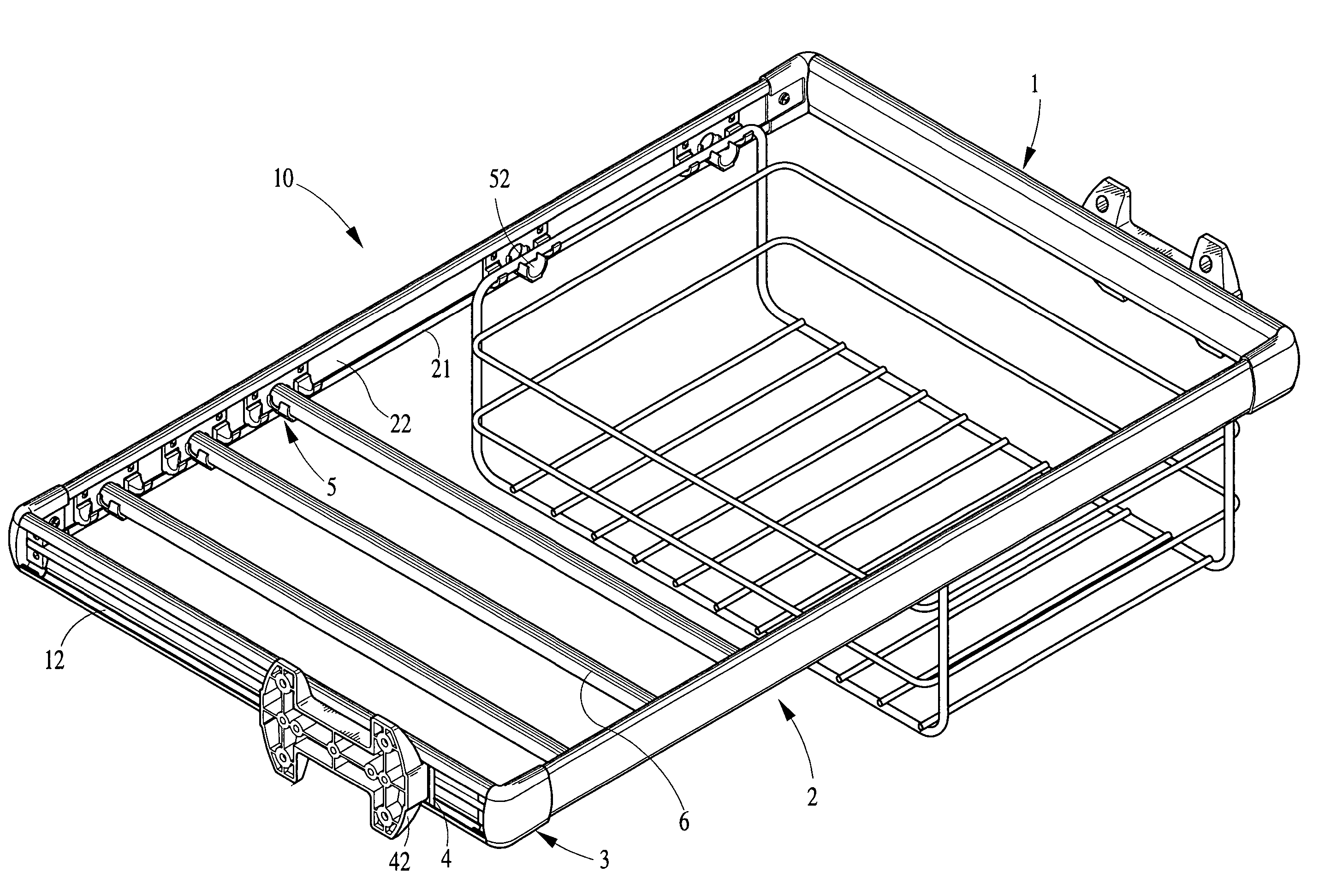
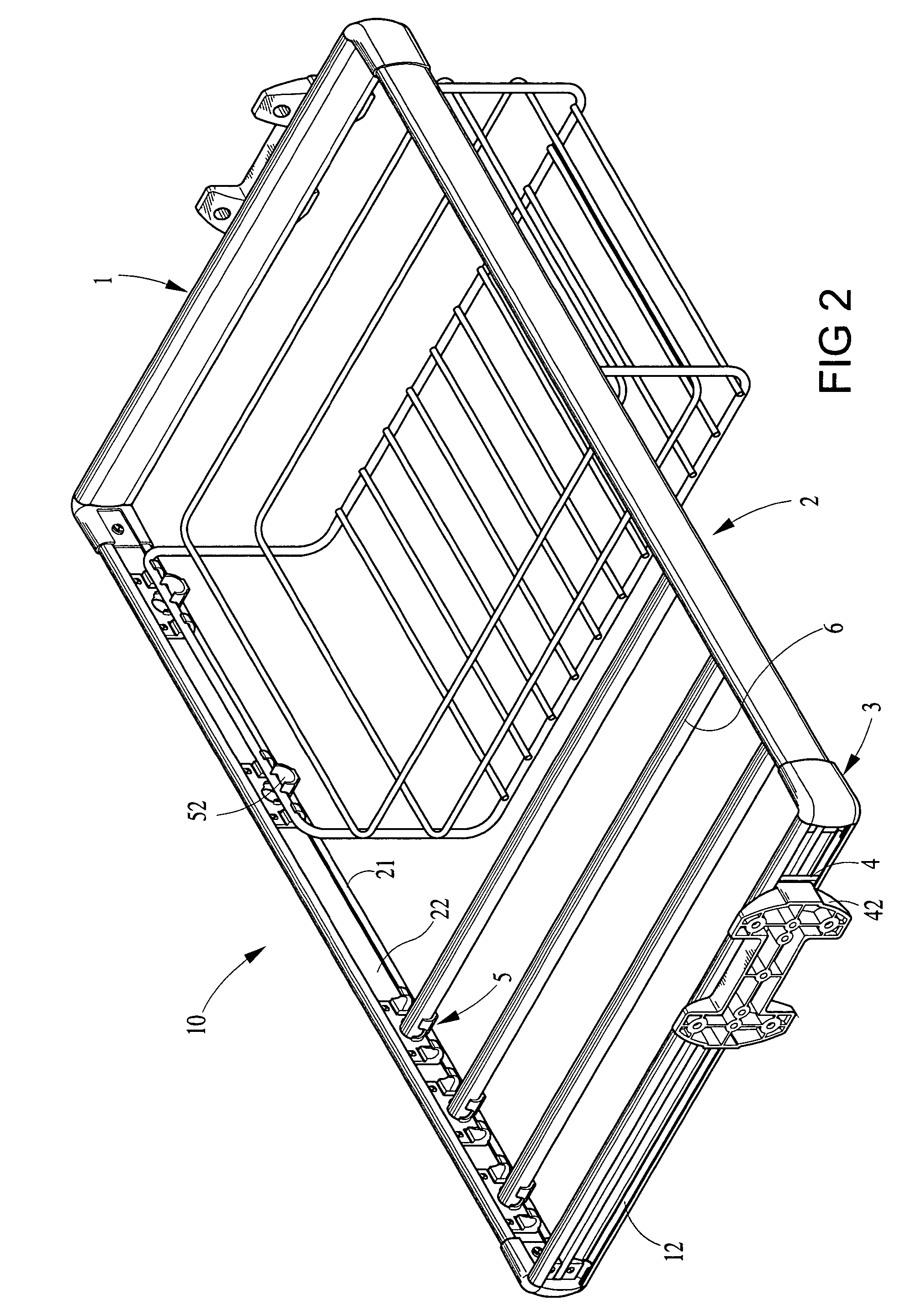
[0015] Referring to FIG. 2 and FIG. 3, the present invention, a basket frame 10, is used in the wardrobe, display window or various cabinets, the basket frame 10 can be pulled out from or pushed back into the above wardrobe or cabinets by means of a pair of sliding rails installed in the wardrobe or cabinets. The basket frame 10 is composed of left and right side frames 1; front and backside frames 2 and four joints 3.

[0016] The left and the right side frames 1 is made of extruding aluminum, the top and bottom end of the left side frame or the right side frame 1 having respectively a hook part 11 so as to form a leading groove 12. A sliding rail 4 is installed respectively on a fixing seat 42 by bolts 41, and the fixing seats 42 being fixed on two inner walls of the wardrobe or cabinet, thus the leading groove 12 of the left and the right side frames 1 can slide on the sliding rails 4, further, the center of the leading groove 12 having a reinforced rib 13 to separate the leading g...


PUM


Abstract

This invention relates to a basket frame, which is composed of a left side frame, a right side frame, a front side frame, a backside frame and four joints. The left side frame and the right side frame have respectively a leading groove which can be slid on two sliding rails installed respectively on two inner walls of the cabinet, and the front side frame and the back side frame having respectively a fitting groove, at least one or more pair of supporting seats being installed opposite in the fitting groove for supporting the hanging rod or hanging basket. One end of the joint have inserting blocks which can be inserted into one end of the left or the right side frame, and the other end other joint having an inserting groove for receiving one end of the front side frame or the back side frame, thus the four side frames can be assembled quickly by the joints, further, the width of the basket frame can be changed by adjusting the inserting depth of the front side frame and the back side frame inserted into the joints.

Description

BACKGROUND OF THE INVENTION [0001] (1) Field of the invention [0002] This invention relates to a basket frame, especially a basket frame that can be assembled quickly and adjusted in width so as to get more convenience in assembling process and improve the appearance of the basket frame. [0003] (2) Description of the Prior Art [0004] The draw basket frame is usually used in the wardrobe, display window or various cabinets, such as shown in FIG. 1, the basket frame 20 being composed of a left side frame, a right side frame 201, a front side rod and a back side rod 202 connected to the left side frame and the right side frame 201. The left side frame and the right side frame 201 can be slid respectively on two sliding rails 203 which are installed on inner wall of the cabinet, thus the rectangular basket frame 20 can be drew out from or pushed into the cabinet freely. The size of the hanging basket 8 is smaller than that of the basket frame 20 hanged and can be hanged on the basket fr...

Claims


Application Information

Patent Timeline
Patent Type & Authority Applications(United States)
IPC IPC(8): A47B88/00A47B88/04
CPCA47B88/00A47B2210/0024A47B2088/0448A47B88/04A47B88/40A47B2088/401A47B88/90
Inventor YANG, ONI
Owner ULIKE
Why Eureka
Try Eureka