Multispectral multi-focal-plane splicing infrared detector control and signal sampling circuit

A technology of infrared detectors and detectors, applied in signal transmission systems, electrical signal transmission systems, instruments, etc., can solve problems such as image distortion, different output times, and reduced imaging quality, so as to simplify design difficulty and design complexity , Improving the effect of image quality

Active Publication Date: 2013-07-24
BEIJING RES INST OF SPATIAL MECHANICAL & ELECTRICAL TECH
View PDF4 Cites 13 Cited by
  • Summary
  • Abstract
  • Description
  • Claims
  • Application Information

AI Technical Summary

Problems solved by technology

[0004] 1) When multiple infrared detectors are used, multiple infrared detectors cannot be controlled cooperatively
When the infrared remote sensing satellite has a large field of view, if the integration time of the infrared detectors at different positions cannot be controlled independently, it may cause image distortion and reduce the imaging quality
[0005] 2) If multiple infrared detectors cannot output images at the same time, first of all, the imaging time of each infrared detector is different, and in the imaging system of multiple infrared detector splicing process, the imaging quality will be reduced
Secondly, the output time of the analog signal of the infrared detector is different, which will increase the difficulty of designing the back-end digital signal processing circuit
[0006] 3) When controlling the infrared detector and sampling the analog signal, the delay of the analog signal must be considered. Most of the existing technologies have a fixed delay time, and there is no command control method, which will increase the design and debugging of the infrared video imaging system. Difficulty, system flexibility is not high
[0007] 4) The existing technology is not conducive to the use of pipeline design and data clock synchronization design methods in the design and implementation of digital circuits, and the system clock frequency is not easy to increase, so the data processing speed and response speed of the system are difficult to improve

Method used


Image

  • Multispectral multi-focal-plane splicing infrared detector control and signal sampling circuit
  • Multispectral multi-focal-plane splicing infrared detector control and signal sampling circuit
  • Multispectral multi-focal-plane splicing infrared detector control and signal sampling circuit

Examples


Embodiment Construction

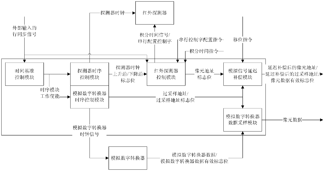
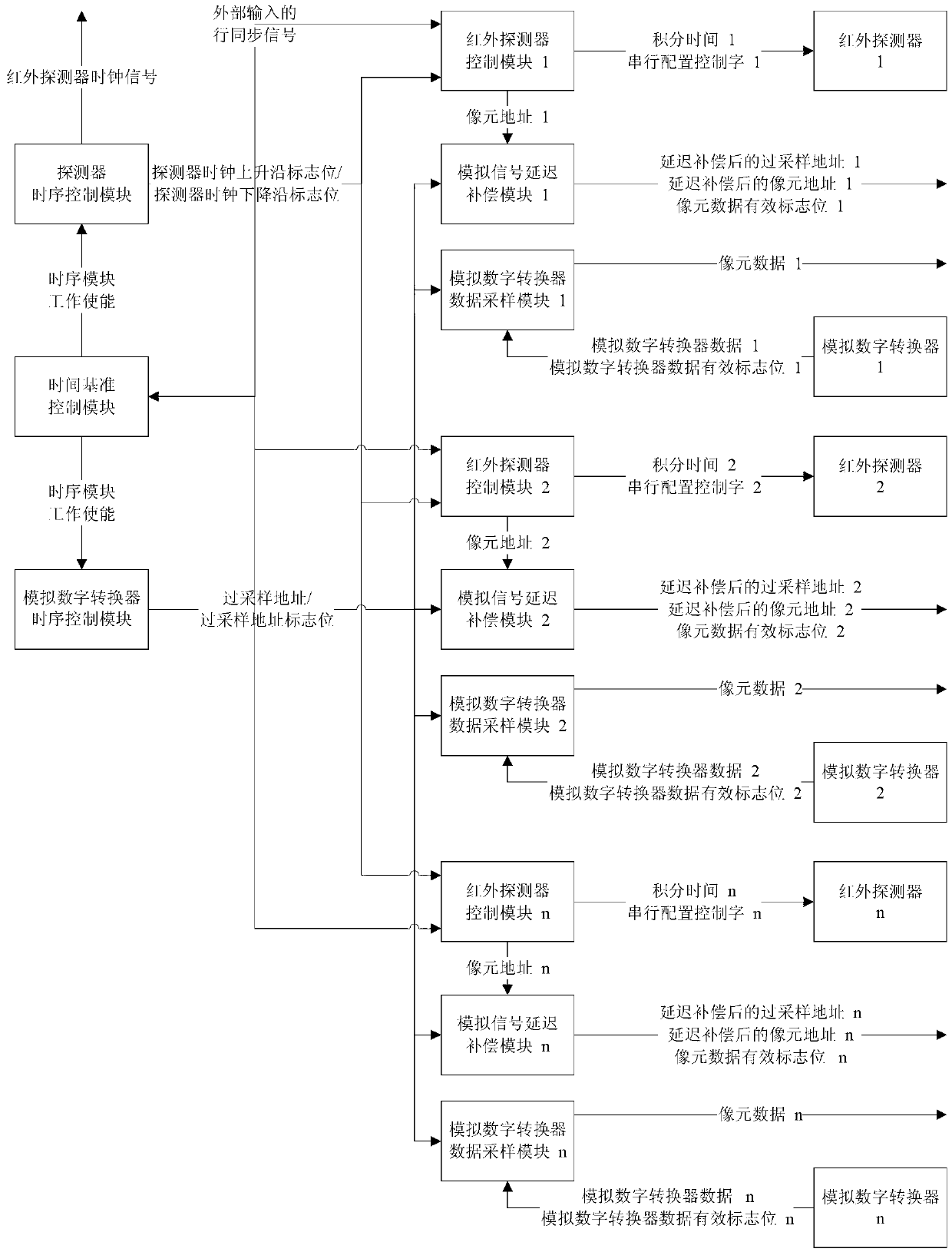
[0031] Such as figure 1 and figure 2 As shown, it is a structural block diagram of the multi-spectrum multi-focal plane splicing infrared detector control and signal sampling circuit proposed by the present invention, including a time reference control module, a detector timing control module, an analog-to-digital converter timing control module, and an infrared detector A control module, an analog-to-digital converter data sampling module, and an analog signal delay compensation module. All the circuits in each module of the multi-spectrum multi-focal plane splicing infrared detector control and signal sampling circuit adopt digital circuit clock synchronization design.

[0032] 1. Key module design

[0033] 1. Time base control module

[0034] Such as image 3 As shown, the time reference control module is composed of a metastable state elimination circuit and a rising edge detection circuit, and generates a timing module work enable signal. The external input horizont...


PUM


Abstract

The invention provides a multispectral multi-focal-plane splicing infrared detector control and signal sampling circuit which comprises a time reference control module, a detector sequential control module, an analog-digital converter sequential control module, an infrared detector control module, an analog-digital converter data sampling module and an analog signal delay compensation module. According to the multispectral multi-focal-plane splicing infrared detector control and signal sampling circuit, a uniform control timing sequence is provided for controlling of multiple infrared detectors through interior timing sequence control logic, the infrared detectors can be controlled independently, and the fact that multiple infrared detectors can output data simultaneously is achieved. In a large field angle infrared remote sensing camera, imaging precision can be improved, image geometric distortion is reduced, design difficulty of a rear-end digital signal processing circuit is simplified, and application of the multispectral multi-focal-plane splicing infrared detector control and signal sampling circuit in the infrared remote sensing camera is achieved.

Description

technical field [0001] The invention relates to a multi-spectral segment and multi-focal plane splicing infrared detector control and signal sampling circuit, which is used in infrared video circuit systems such as infrared remote sensing cameras to control the infrared detector and the sampling signal circuit. Background technique [0002] With the development of infrared detector manufacturing technology, infrared imaging system has been widely used in national defense, remote sensing, medical and other fields. [0003] At present, the infrared detector used in the infrared video system is basically an infrared detector. In order to improve the resolution of the infrared imaging system, the process of splicing multiple infrared detectors can be used to double the resolution of the infrared imaging system. But it also introduces many new technical problems. Designing multiple infrared detector imaging systems using existing technologies has several drawbacks: [0004] 1) ...

Claims


Application Information

Patent Timeline
Patent Type & Authority Applications(China)
IPC IPC(8): H03M1/54
Inventor 刘涛王华魏志勇
Owner BEIJING RES INST OF SPATIAL MECHANICAL & ELECTRICAL TECH
Why Eureka
Try Eureka