Method for contactless capacitive thickness measurements

A thickness measurement, non-contact technology, applied in the direction of electric/magnetic thickness measurement, electromagnetic measurement device, measurement device, etc., can solve problems such as inapplicability

Active Publication Date: 2010-07-28
PLAST CONTROL GMBH
View PDF2 Cites 12 Cited by
  • Summary
  • Abstract
  • Description
  • Claims
  • Application Information

AI Technical Summary

Problems solved by technology

However, this method is not suitable for non-contact measurements when the air gap

Method used


Image

  • Method for contactless capacitive thickness measurements
  • Method for contactless capacitive thickness measurements
  • Method for contactless capacitive thickness measurements

Examples


Embodiment Construction

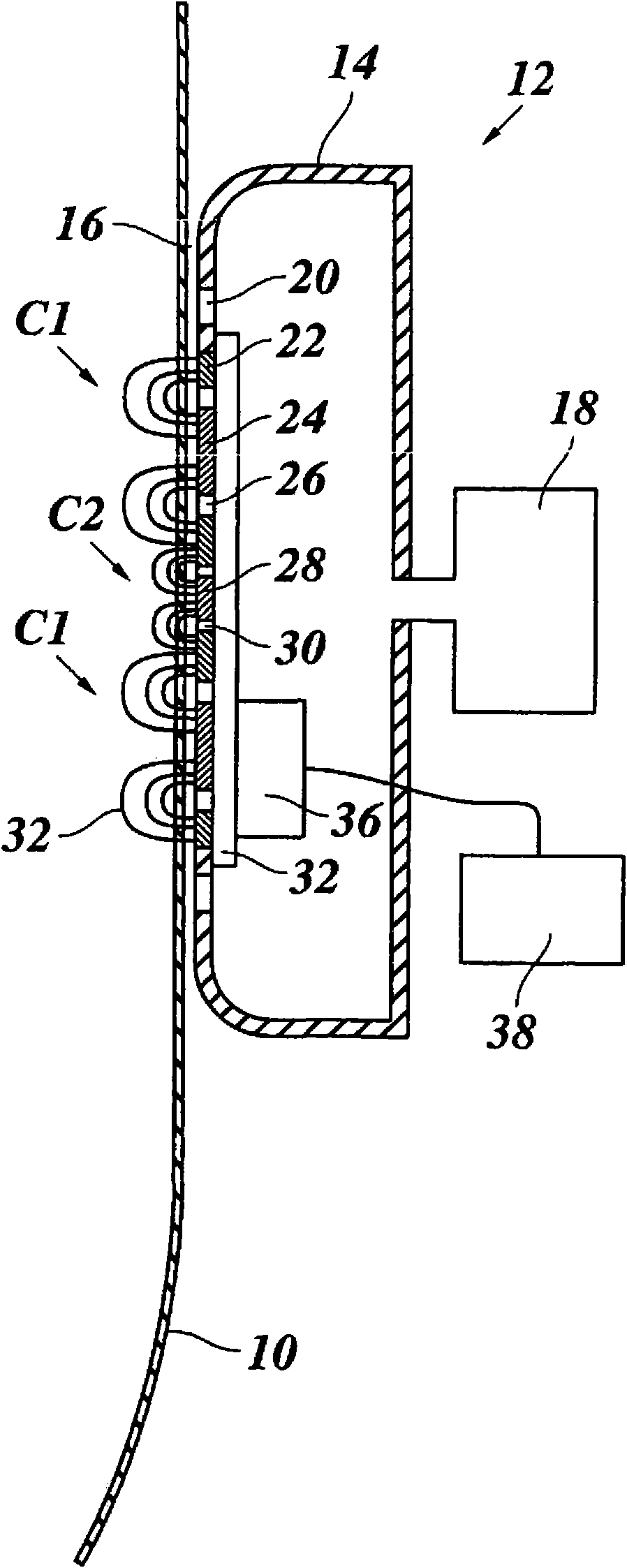
[0022] figure 1 A portion of a film 10, such as a bubble, is shown in schematic cross-section, extruded by a bubble extruder. The thickness of the film 10 will be measured non-contact by means of a capacitive measuring device 12 . For this purpose, the measuring head 14 of the measuring device is arranged on the periphery of the bubble in such a way that a narrow air gap 16 is formed with the constantly upwardly moving film. To stabilize the air gap 16 , the measuring head 14 is connected to a blower 18 , by means of which air is blown out of the measuring head 14 through the opening 20 in the direction of the film 10 . The measuring head can be slightly offset from the membrane so that the membrane will "suspend" on a cushion of air.

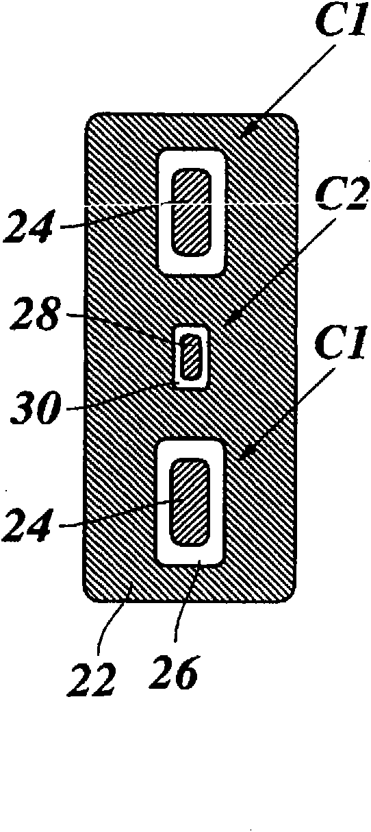
[0023] Integrated in the wall of the measuring head 14 facing the membrane 10 is a capacitor array forming two capacitors C1 and C2. The capacitor array has been shown in the figure 2 front view in . For reasons of symmetry, capacitor C1 ...


PUM


Abstract

A method for contactless capacitive thickness measurement of a flat material (10) that is placed in the fringe field (32) of a capacitor (C1, C2), with simultaneous measurement of the width L of an air gap (16) between the flat material and the capacitor plates, characterised in that the capacities gL, kL of two capacitors (C1, C2) are measured whose fringe fields (32) decay at different rates towards the flat material (10), and in that both, the thickness D of the flat material (10) and the width L of the air gap (16) are determined on the basis of the condition that, for each capacitor (C1, C2), the measured capacity gL, kL is equal to the integral of the capacity gradient g', k' over the thickness of the flat material (10).

Description

technical field [0001] The present invention relates to a method for non-contact capacitive thickness measurement of a planar material placed in the fringing field of a capacitor and simultaneously measuring the width of the air gap between the planar material and the plates of the capacitor. Background technique [0002] A method of this type is described in EP 1 681 531 A1. A typical application example of this method is the measurement and feedback control of film thickness during extrusion of flat films or bubbles. Since the measurement takes place in the scattered field of the capacitor and, therefore, both plates of the capacitor are on the same side of the membrane, measurements of closed bubbles can also be easily achieved. Since there is always a certain air gap between the measuring head carrying the capacitor plates and the membrane surface, non-contact measurements have the advantage of avoiding damage to the membrane surface. In this case, however, the measure...

Claims


Application Information

Patent Timeline
IPC IPC(8): G01B7/06
CPCG01B7/087
Inventor 斯特凡·科纳曼马库斯·施泰因
Owner PLAST CONTROL GMBH
Why Eureka
Try Eureka