Programmable output buffer

a buffer and output technology, applied in the field of output buffers, can solve the problems of large undesired ground and power bounce in the supply rails and ringing in the system, dispersing extra power that must be avoided, and further deterioration of output delays, so as to reduce noise, control output delays, and drive more effectively

Active Publication Date: 2005-01-06
STMICROELECTRONICS PVT LTD
View PDF5 Cites 18 Cited by
  • Summary
  • Abstract
  • Description
  • Claims
  • Application Information

AI Technical Summary

Benefits of technology

The disclosed embodiments of the invention provide output delays for all driving strengths comparable to the smallest delay that occurs for maximum driving strength without generating any extra noise and to minimizing the noise generated for higher driving strengths. In addition, the invention controls output delays by optimizing delays and noise for various driving strengths and slew rates. The invention further provides, for different driving strengths and slew rates, an optimal balance between the output delays and the noise generated.

Problems solved by technology

For driving a large capacitive load, the output buffer needs to have larger output drive strength that allows larger current to be sinked and sourced by the load for smaller output transition times. A smaller drive strength would increase the output transition times. On the other hand for a small capacitive load, the output buffer requires only a small output drive strength, and a higher drive strength buffer driving a small load would generate large transient currents resulting in large undesired ground and power bounce in the supply rails and ringing in the system.
Also, it dissipates extra power that must be avoided as integrated circuits become smaller and faster.
Whereas in case of a slow slew rate the output delays further deteriorate.
This implies that the output delays and supply noise vary widely for various drive strengths and slew variations, and that for lower driving strengths the delays are worse while noise is much lower than the maximum noise that the system can tolerate.

Method used


Image

  • Programmable output buffer
  • Programmable output buffer
  • Programmable output buffer

Examples


Embodiment Construction

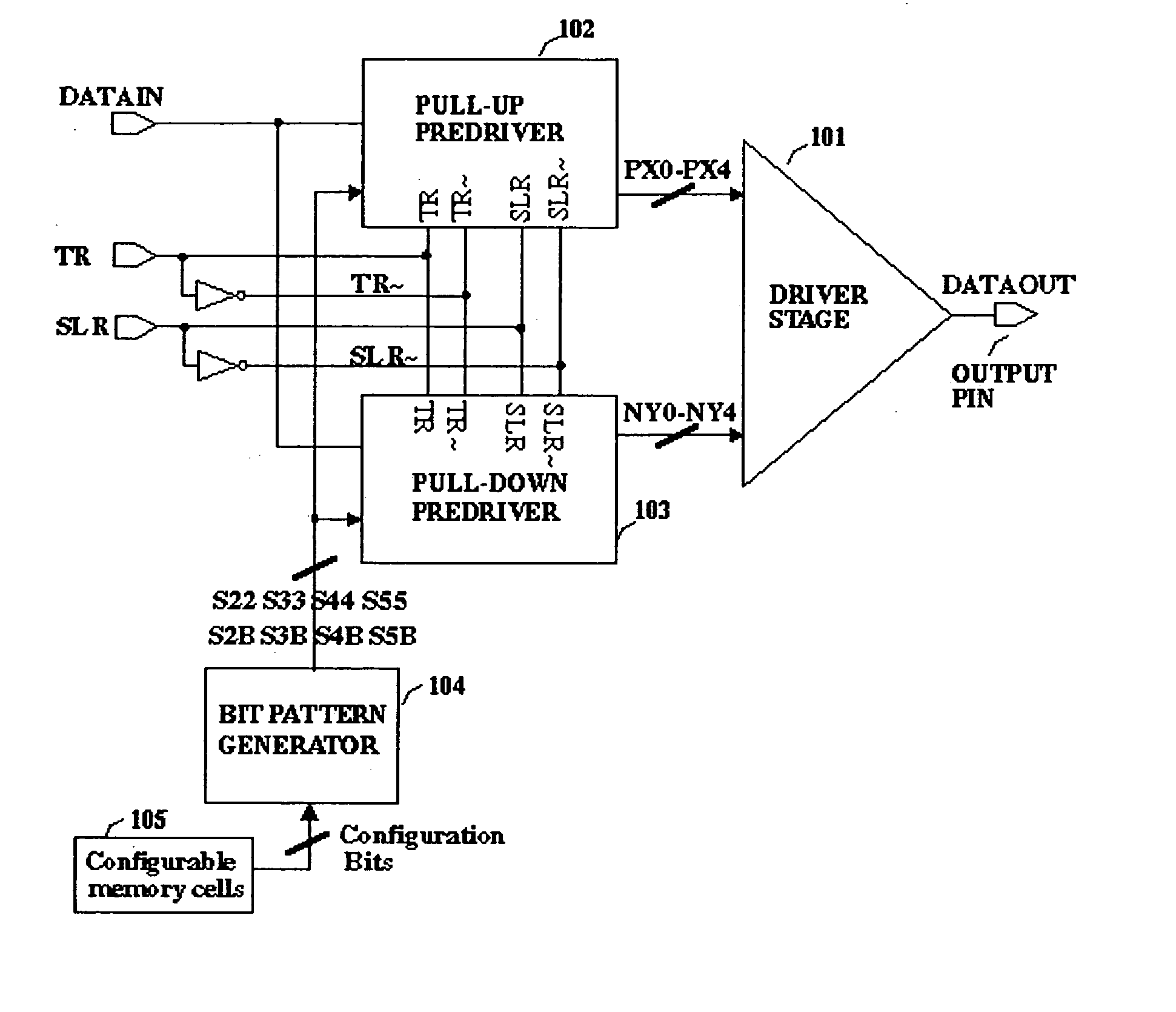
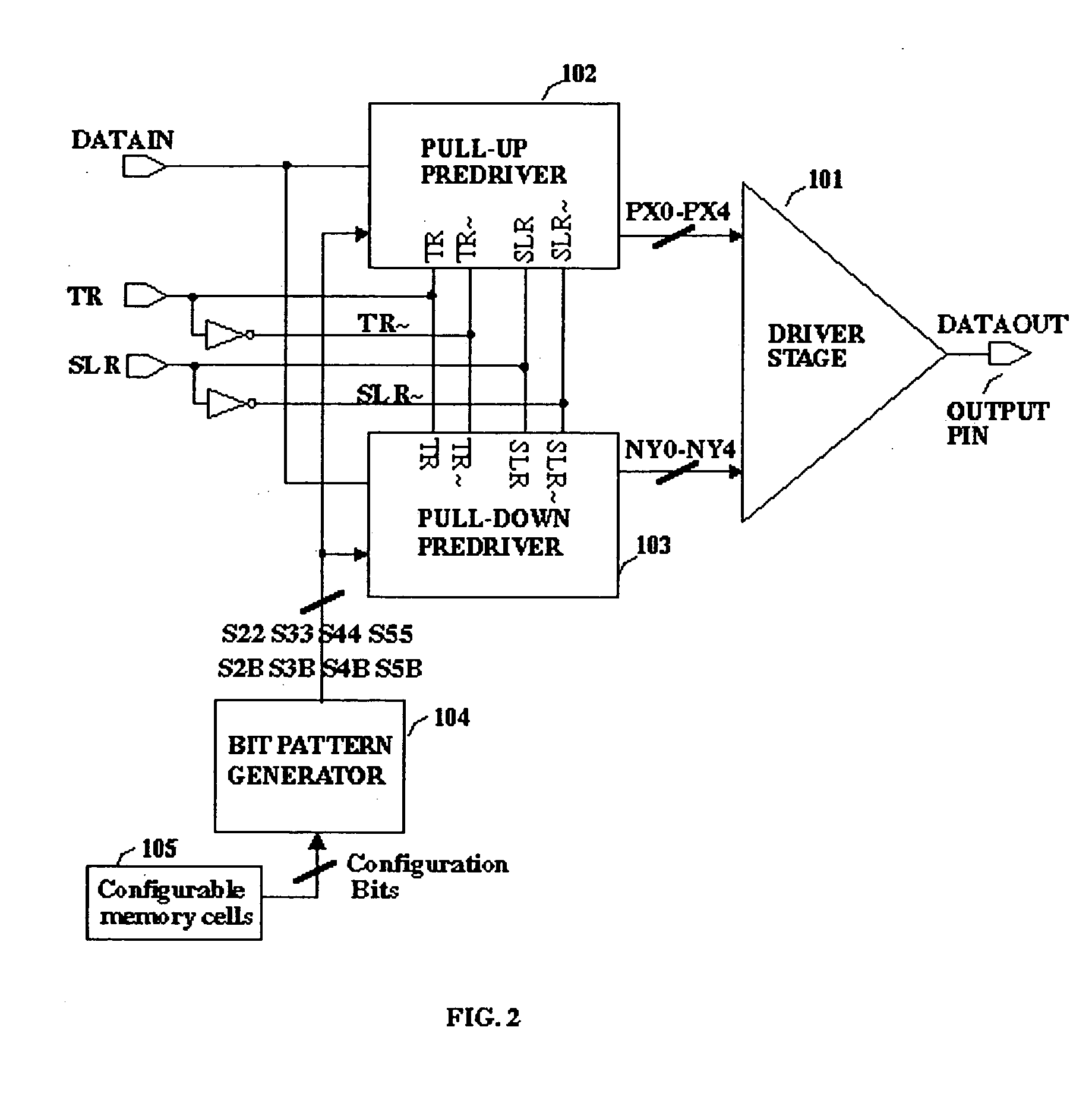
Referring to FIG. 2, shown therein is an embodiment of programmable drive strength output buffer in accordance with an embodiment of the present invention. The instant invention provides a tri-state output buffer with variable slew rate. The output buffer includes a pull-up predriver 102 and a pull-down predriver 103 having their outputs PX-PX4 and NY0-NY4 driving a driver stage 101. The predrivers have control signals TR, SLR, TR˜, and SLR˜ and receive input data DATAIN and a bit configuration pattern from a bit pattern generator 104. The bit pattern generator 104 generates the bit pattern depending upon the input it receives from a configuration memory cell 105.

The output pin of the driver stage is left floating with all the transistors within the driver stage switched off when the control signal TR is high. When the control signal TR is low, the output buffer is enabled and data at the DATAIN is transmitted to the output pin at a selected output drive strength and slew rate. T...


PUM


Abstract

A programmable output buffer providing variable drive strength and slew rate for a given noise limit that includes a driver stage that generates the output of the buffer and a plurality of selectively enabled switching elements, at least a predriver stage providing a plurality of selectable switching elements that enables the selected drive stage switching elements, and a selection means that enables the required predriver switching elements in the desired sequence to provide the desired drive strength and slew rate.

Description

BACKGROUND OF THE INVENTION 1. Field of the Invention The invention relates to an output buffer and, more particularly, a programmable output buffer with variable driving strengths and variable slew rate. 2. Description of the Related Art Output buffers in CMOS integrated circuits are used to couple data and control signals to external pins that need to drive different types of load, typically capacitive in nature, hence the output transition timing are dependent on the capacitance value of the load and the driving strength of output buffer. For driving a large capacitive load, the output buffer needs to have larger output drive strength that allows larger current to be sinked and sourced by the load for smaller output transition times. A smaller drive strength would increase the output transition times. On the other hand for a small capacitive load, the output buffer requires only a small output drive strength, and a higher drive strength buffer driving a small load would gener...

Claims


Application Information

Patent Timeline
Patent Type & Authority Applications(United States)
IPC IPC(8): H03K17/16
CPCH03K17/164
Inventor AHMAD, ADEEL
Owner STMICROELECTRONICS PVT LTD
Why Eureka
Try Eureka