Antenna system

a technology of antenna system and antenna, applied in the direction of antenna details, substation equipment, antennas, etc., can solve the problems of inability to produce auxiliary antenna patterns with no main lobe, inability to completely cancel sidelobes, and limited wireless network capacity

Inactive Publication Date: 2005-01-06
ANDREW CORP
View PDF17 Cites 36 Cited by
  • Summary
  • Abstract
  • Description
  • Claims
  • Application Information

AI Technical Summary

Problems solved by technology

The capacity of wireless networks is often found to be interference limited.
A problem with this approach is that the sidelobes will not be perfectly cancelled.
Also, it is not possible to produce an au

Method used


Image

  • Antenna system
  • Antenna system
  • Antenna system

Examples


Embodiment Construction

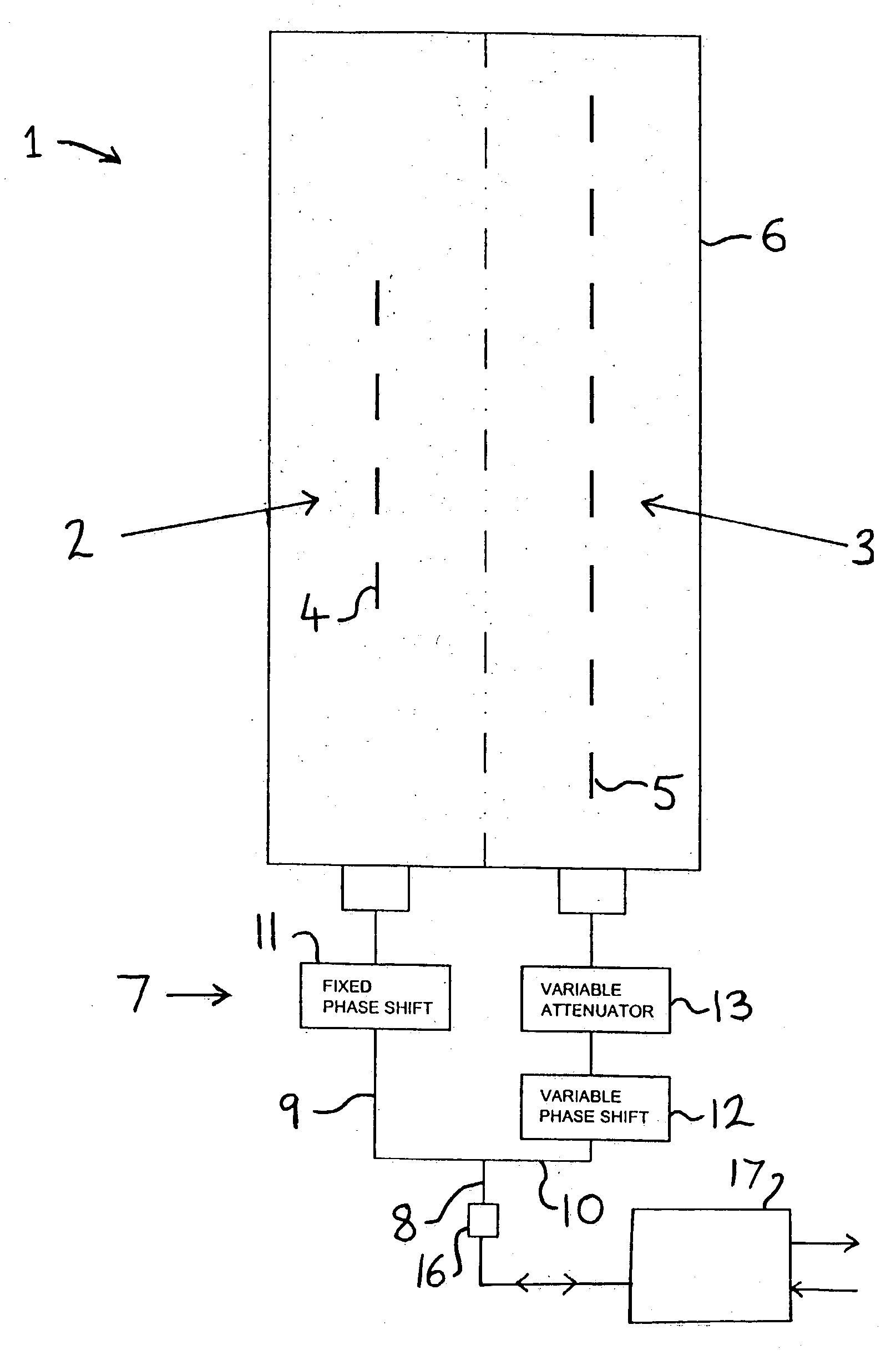
[0006] The exemplary embodiment provides, in a first aspect, an antenna system including a coverage antenna with a coverage beam pattern; and an auxiliary antenna with an auxiliary beam pattern, wherein said auxiliary beam pattern has a mainlobe with: [0007] a) an amplitude lower than an amplitude of a mainlobe of said coverage beam pattern; [0008] b) a width lower than a width of said mainlobe of said coverage beam pattern; [0009] c) a phase substantially opposite to a phase of a sidelobe of said coverage beam pattern; and [0010] d) a direction which is selected so as to at least partially suppress said sidelobe.

[0011] The exemplary embodiment provides, in a second aspect, an antenna system including a coverage antenna with a coverage beam pattern; an auxiliary antenna with an auxiliary beam pattern having a mainlobe with an amplitude, width, and direction selected so as to modify said coverage beam pattern; and a transmit / receive system for receiving uplink signals from said ante...


PUM


Abstract

An antenna system including a coverage antenna (2) with a coverage beam pattern; and an auxiliary antenna (3) with an auxiliary beam pattern. The auxiliary beam pattern is arranged to perform sidelobe suppression, null steering, null addition, or null-fill. In the case where the auxiliary antenna is used to perform sidelobe suppression, the auxiliary beam pattern has a mainlobe with: an amplitude lower than an amplitude of a mainlobe of said coverage beam pattern; a width lower than a width of said mainlobe of said coverage beam pattern; a phase different to a phase of a sidelobe of said coverage beam pattern; and a direction which is selected so as to at least partially suppress said sidelobe.

Description

FIELD OF THE INVENTION [0001] The present invention relates to an antenna system, typically but not exclusively for use in a mobile communications wireless network. DESCRIPTION OF THE RELATED ART [0002] The capacity of wireless networks is often found to be interference limited. Such interference predominantly comes from nearest neighbour cells using the same frequency. This problem is illustrated in FIG. 10, which shows a vertical section through a first base station 50 and nearest neighbour base station 51. Each base station has an antenna with a respective mainlobe 52,53, first upper sidelobes 54,55 and second upper sidelobes 56,57. At the downtilt angle shown in FIG. 10, it can be seen that the first upper sidelobes 54,55 are directed horizontally. As a result, the sidelobe 55 acts an interference source for the receive channel of the base station 50, and the sidelobe 54 acts an interference source for the receive channel of the base station 51. Similarly, the second upper sidel...

Claims


Application Information

Patent Timeline
IPC IPC(8): H01Q1/24H01Q3/26
CPCH01Q3/2629H01Q1/246
Inventor ELLIOT, ROBERT DOUGLASLINEHAN, KEVIN ELDON
Owner ANDREW CORP
Why Eureka
Try Eureka