
Infusion device

a technology of infusion device and structure, which is applied in the direction of intravenous device, catheter, other medical devices, etc., can solve the problems of inability to keep the cross sectional area, difficulty in insertion of tubular parts into the body, and inability to stop the flow of blood, so as to achieve convenient insertion into the body and reliably secure

Active Publication Date: 2005-01-06
ASAHI INTECC CO LTD +1
View PDF27 Cites 27 Cited by
  • Summary
  • Abstract
  • Description
  • Claims
  • Application Information

AI Technical Summary

Benefits of technology

[0008] The present invention was arrived at in consideration of the foregoing matters, and it is an object thereof in an embodiment to provide an infusion device having a tubular member in which at least three lumens are provided, which can be easily inserted into the body and which allows the flow of blood through a blood vessel to be reliably secured even if the tubular member has been inserted into that blood vessel.

Problems solved by technology

In infusion devices having such a structure, it is not possible to keep the cross sectional area of the tubular member perpendicular to its axial direction from becoming large.
For that reason, when using such infusion devices there is the concern that depending on the site in the body to which it is to be inserted it may be difficult to insert the tubular member into the body, even if the tubular member has an annular profile perpendicular to its axis such that it can be inserted into the body as smoothly as possible.
Moreover, there is also a concern that the flow of blood may be arrested when the tubular member has been inserted into a blood vessel, for example.

Method used


Image

  • Infusion device
  • Infusion device
  • Infusion device

Examples


Embodiment Construction

[0060] To make the present invention more readily apparent, configurations of infusion devices according to embodiments of the present invention are described in detail below with reference to the drawings. However, the present invention should not be limited to these embodiments.

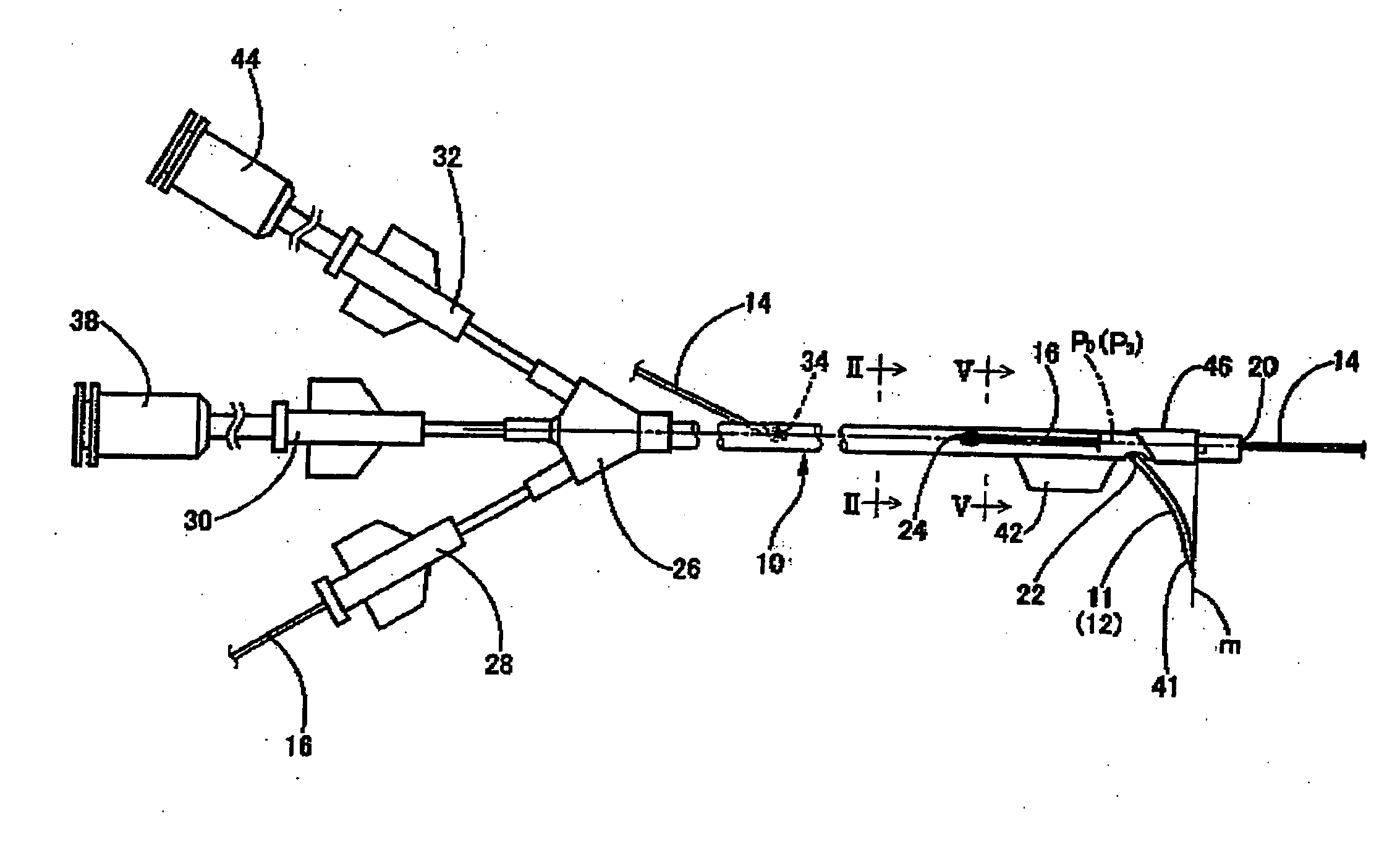
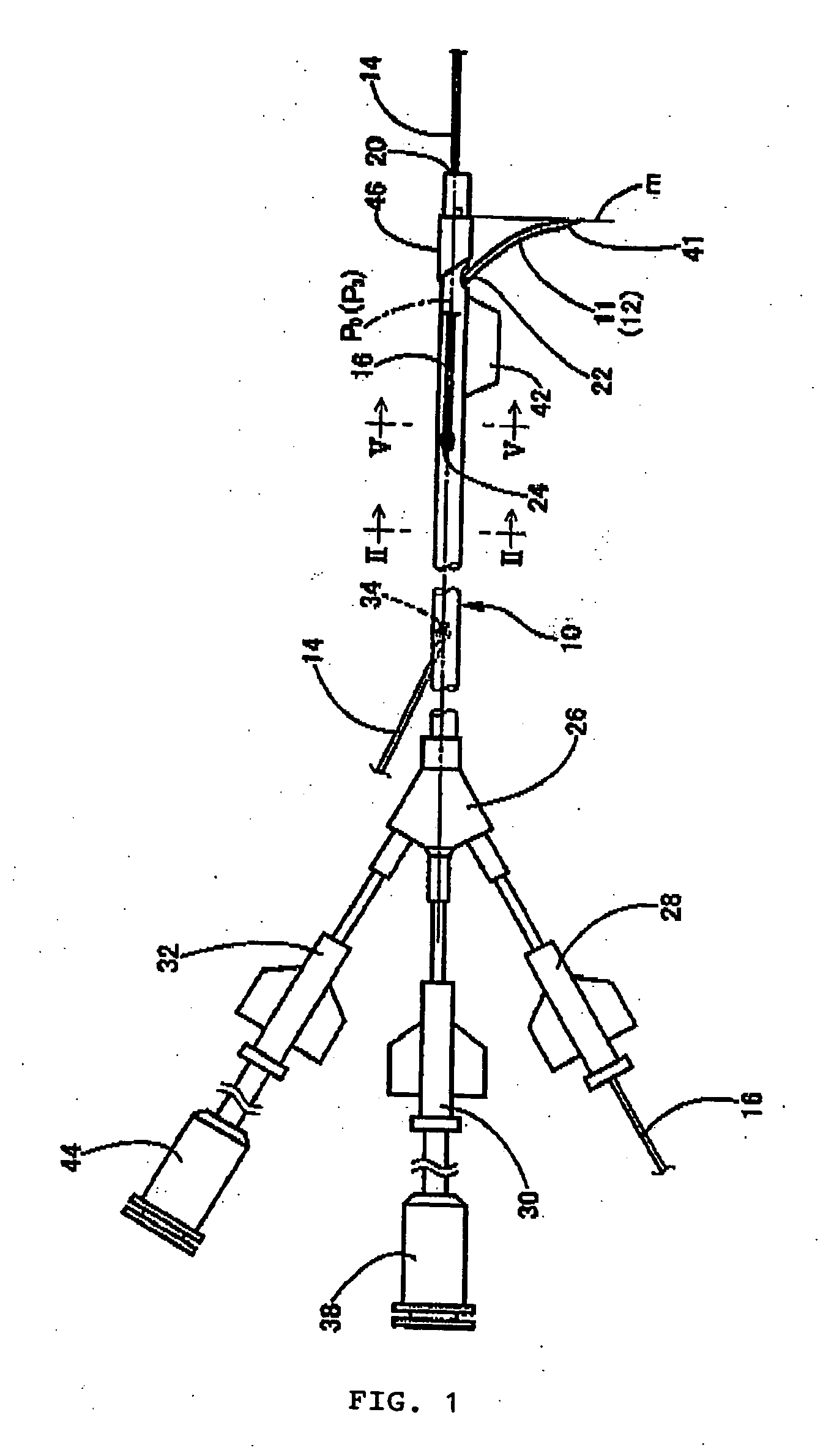
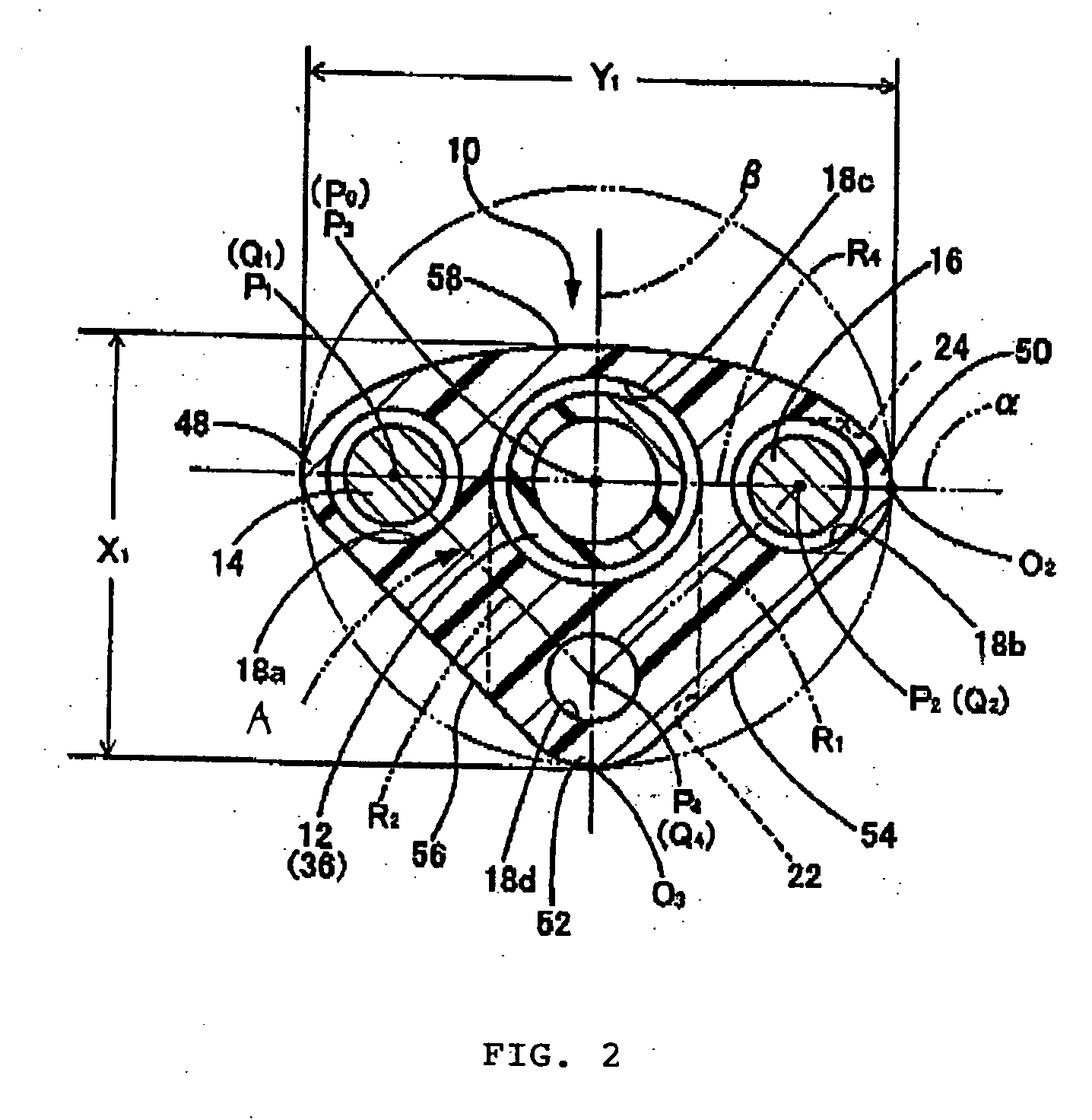
[0061] First, FIG. 1 and FIG. 2 schematically show a front view and a vertical section, respectively, of an infusion catheter that is employed to infuse a reagent to a lesion portion in cardiac muscle as one embodiment of the infusion device having the structure according to the present invention. In FIGS. 1 and 2, reference numeral 10 denotes a catheter member made of an elongate tubular member serving as the tubular member, into which a needle-shaped tube member 12 whose tip portion is a sharp needle portion 11, a first guide wire 14, and a second guide wire 16 each are inserted in such a manner as to allow movement thereof in the axial direction.

[0062] More specifically, the catheter member 10 has a le...


PUM


Abstract

It is an object of the present invention to provide an infusion device that can be easily inserted into the body and that when inserted into a blood vessel reliably ensures the flow of blood. The infusion device is provided with a needle-shaped tube member having a sharp tip in any one lumen of the three lumens provided within a tubular member that can be inserted into the body in such a manner that it can move axially, an extrusion aperture provided in the tubular member through which the needle-shaped tube member is extruded, and a reagent supplier for supplying a predetermined reagent into the needle-shaped tube member. Additionally, recessed portions extending axially are formed in an outer circumferential surface of the tubular member in such a manner that the cross sectional shape perpendicular to the axial direction of the tubular member is a shape in which at least a portion of the outer circumference of an annular shape has been recessed radially inward.

Description

BACKGROUND OF THE INVENTION [0001] 1. Field of the Invention [0002] The present invention generally relates to the structure of infusion devices for infusing a predetermined reagent to lesion portions, for example, in body tissue. [0003] 2. Description of the Related Art [0004] Conventionally, medical devices such as catheters have been introduced into tubular organs in the body such as blood vessels, the alimentary canal, and the ureters to perform various treatments, tests, and procedures, for example. More recently, treatment and procedures in which infusion devices such as infusion catheters have been used to infuse a predetermined liquid medicine into lesion portions in body tissues have been performed (see JP 2001-104487A and JP 2001-299927A). [0005] That is, as is well known in the art, such infusion catheters are constituted by a tubular catheter member into which a needle-shaped tube member made of a narrow tube capable of conducting a predetermined reagent and having a sha...

Claims


Application Information

Patent Timeline
Patent Type & Authority Applications(United States)
IPC IPC(8): A61M5/178A61M5/14A61M25/00A61M31/00
CPCA61M25/0084
Inventor KATOH, OSAMUSHIMOGAMI, MANABU
Owner ASAHI INTECC CO LTD
Learn More