Low profile surgical retractor

a retraction device, low-profile technology, applied in the field of medical devices, can solve the problems of affecting the surgeon's work efficiency, affecting the surgeon's ability to perform surgery, occupying a considerable amount of space, etc., and achieve the effect of inexpensive manufactur

Active Publication Date: 2007-06-12
EDWARDS LIFESCIENCES LLC
View PDF7 Cites 911 Cited by
  • Summary
  • Abstract
  • Description
  • Claims
  • Application Information

AI Technical Summary

Benefits of technology

[0006]Therefore, it would be advantageous to have a retraction device that performs the necessary functions of a conventional retractor without superfluous structure in the space outside the area being retracted. It would be further advantageous for such a device to be capable of inexpensive manufacture. The latter would make it economically feasible to use each device only once. Accordingly, this eliminates the need for cleaning and sterilization between uses, and the risk of microbial cross-contamination among subsequent users from inadequate cleaning and sterilization.
[0007]The invention described herein provides a low profile retractor that is designed to minimize the space occupied by the retractor. The blades and frame of the retractor can occupy the same space or be the same physical member, so that there will be few or no structural members outside the region being retracted. The blade members can be molded or machined separately and hinged together, or the blades can be attached as one piece and flex at the connection joints as a living hinge, e.g., when the blades are made of plastic. Additionally, the retractor can be easily inserted into the body via an incision for operations involving any type of retractor, e.g., atrial retraction.
[0008]In one aspect of the invention, a surgical retractor includes at least two retractor blade components joined pivotally, a cable, a deployed length of which is guided by the at least two retractor blade components, and a winding mechanism carried by at least one of the at least two retractor blade components for shortening the deployed length of the cable to cause the at least two retractor blade components to transition from a closed position to an open position.
[0010]In another aspect of the invention, a surgical method includes inserting a retractor in a closed position into a body though a first incision in the body, wherein the retractor includes at least two retractor blade components joined pivotally, a cable, a deployed length of which is guided by the at least two retractor blade components, and a winding mechanism carried by at least one of the at least two retractor blade components, and operating the winding mechanism from a portion of a handle that is outside the body, where the handle is coupled to the winding mechanism, to shorten the deployed length of the cable to cause the at least two retractor blade components to transition from the closed position to an open position.
[0011]In another aspect of the invention, a surgical method includes positioning a retractor in an at least partially closed position for retracting tissue of a body, wherein the retractor includes at least two retractor blade components joined pivotally, a cable, a deployed length of which is guided by the at least two retractor blade components, a winding mechanism carried by at least one of the at least two retractor blade components, and a handle coupled to the winding mechanism, and operating the winding mechanism using the handle to shorten the deployed length of the cable to cause the at least two retractor blade components to transition from the closed position to an open position to retract the tissue.

Problems solved by technology

However, such retractors have the drawbacks that they tend to be large, bulky devices that occupy a considerable amount of space at the surgical site.
This impedes the surgeon's access to and visualization of the surgical site, making any procedure more difficult and / or time consuming.

Method used


Image

  • Low profile surgical retractor
  • Low profile surgical retractor
  • Low profile surgical retractor

Examples


first embodiment

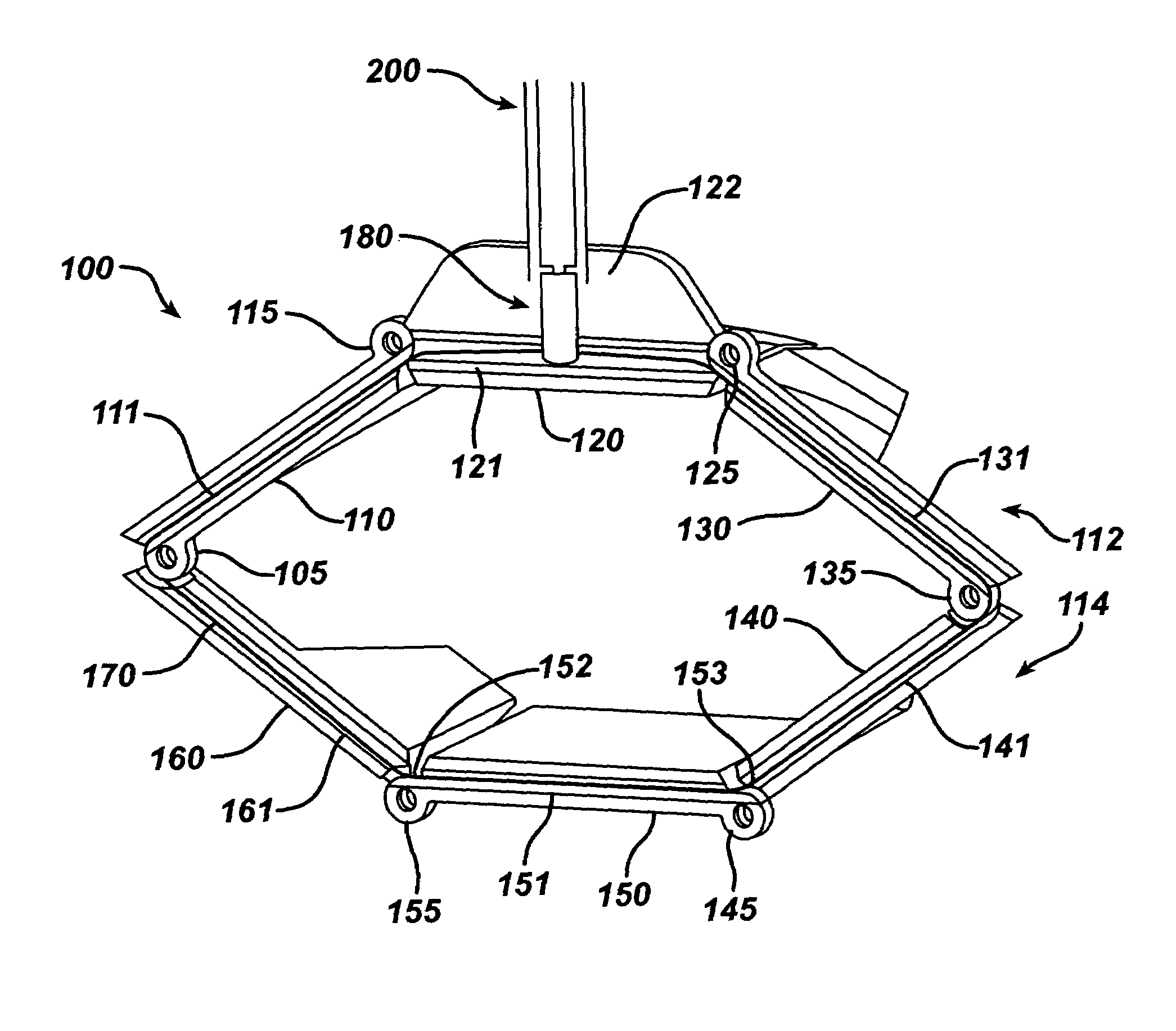
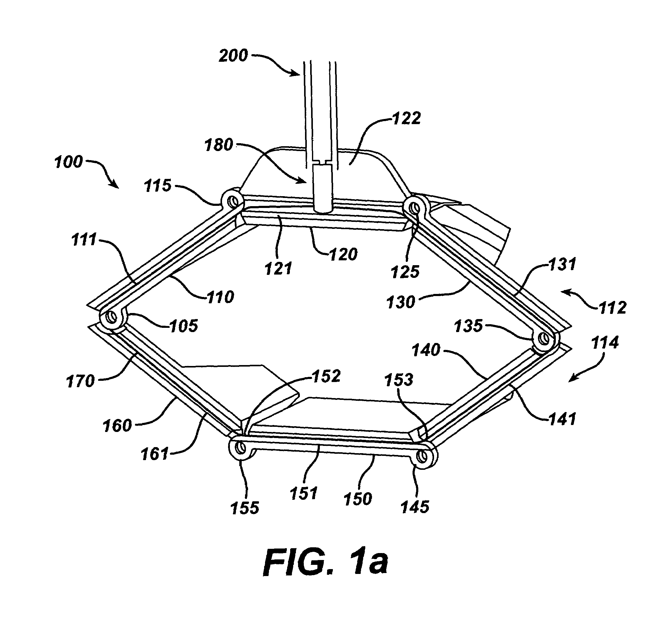
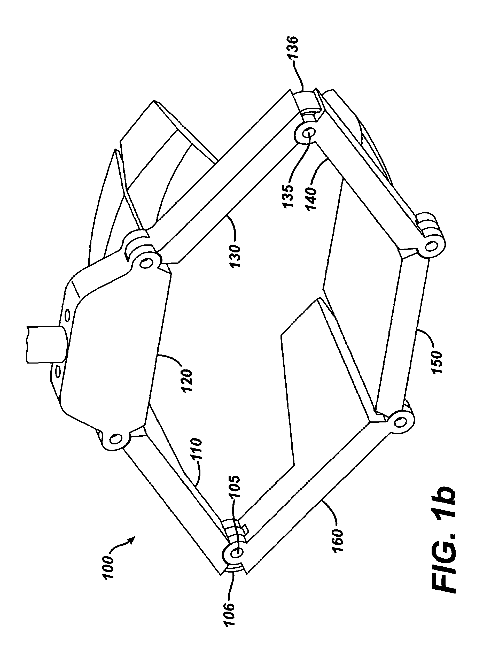
[0039]FIG. 1(a) shows a perspective cutaway view of a retractor according to the present invention. The retractor 100 includes a number of retractor blade components 110, 120, 130, 140, 150 and 160, in this case six. Each of retractor blade components 110, 120, 130, 140, 150 and 160 are joined pivotally at pivot points 105, 115, 125, 135, 145 and 155, and together form a periphery of the retractor 100. The retractor blade components may be joined end to end, for instance. Neighboring retractor blade components may be separate components that are fixed together, e.g., by pins, or may be formed from a common material, in which case the pivot points may comprise living hinges. A living hinge generally includes a weakened, flexible area of material between neighboring retractor blade components.

[0040]A cable 170 has a deployed length that is guided by and / or through, or alternately attached to, one or more of the retractor blade components 110, 120, 130, 140, 150 and 160. In one possibl...

second embodiment

[0062]FIG. 3 shows a perspective cutaway view of a retractor 300 according to the present invention. Here, one end 171 of the cable 170 terminates at a fixed point, such as at a ball or block structure 310, which is carried by the retractor blade component 120. The other end 172 of the cable 170 is attached to the winding mechanism 180. In this approach, only one end of the cable is wound up by the winding mechanism 180, so twice as many rotations of the turn knob are required compared to the embodiment of FIGS. 2(a) and 2(c) to achieve the same amount of winding or unwinding. This may be desirable since it provides a finer control of the winding and unwinding. Note that, in this and other embodiments, gearing may be used so that the rotation of the turn knob 210 relative to the winding mechanism 180 is greater than or less than 1:1.

third embodiment

[0063]FIG. 4 shows a perspective cutaway view of a retractor 400 according to the present invention. Here, one end of the cable 170 remains attached to the fixed structure 310, while the other end of the cable is wound around posts or winding pins 410 and 420 which are arranged in the retractor blade component 120, before terminating at the winding mechanism 180. Due to the 180-degree turns about the pins 410 and 420, a moderate amount of friction between the cable 170 and the pins 410 and 420 that prevents the cable from unwinding due to the force of the retracted tissue, yet still allows the cable to be wound up or unwound by the turn knob 210 with relative ease. Such an approach avoids the need for a ratchet mechanism to prevent the retractor from closing, e.g., when the handle is removed from the retractor blade component 120. The amount of friction will depend on factors such as the size and material of the cable 170 and pins 410 and 420, and the number of turns of the cable 17...


PUM


Abstract

A compact, low-profile surgical retractor (100) avoids the need for a bulky frame. The retractor includes retractor blade components (110, 120, 130, 140, 150, 160) joined pivotally. A cable (170) is guided by each retractor blade component. A winding mechanism (180), such as a spool, is carried by one of the retractor blade components (120) for winding up the cable to cause the retractor blade components to transition from a closed position to an open position. The winding mechanism may be actuated by a detachable handle (200). The retractor blade components may be unitary, injection-molded pieces. The retractor blade components may be fixed pivotally, such as by pins, or pivotally joined by living hinges. A less-invasive surgical method is also provided in which the retractor is inserted into the body through an incision.

Description

BACKGROUND OF THE INVENTION[0001]1. Field of Invention[0002]The invention relates to the field of medical instruments, and more particularly, to a low profile, compact retraction device that avoids the need for a bulky frame, and to surgical methods of using such a device.[0003]2. Description of Related Art[0004]Surgical retractors are frequently required, and equally commonly used, in surgical procedures to hold back the edges of superficial tissues and / or organs, allowing the surgeon to expose underlying anatomic structure to which she requires access. Conventional retractors are comprised of a stainless steel rack and pinion frame, with retractor blades mounted the frame, and a crank handle or similar means mounted to the frame or the blades in order to position the blades along the rack, opening and closing the retractor.[0005]However, such retractors have the drawbacks that they tend to be large, bulky devices that occupy a considerable amount of space at the surgical site. Thi...

Claims


Application Information

Patent Timeline
Patent Type & Authority Patents(United States)
IPC IPC(8): A61B1/32
CPCA61B1/32A61B17/0218
Inventor DOUGLASVANERMAN, HUGO
Owner EDWARDS LIFESCIENCES LLC
Why Eureka
Try Eureka