Semi-constrained ankle joint prosthesis and its method of implantation

a prosthesis and ankle joint technology, applied in the field of ankle prosthesis, can solve the problems of poor understanding, difficulty in integrating with other associated parts of the foot and leg, and reputation damage of ankle arthroplasty

Active Publication Date: 2005-01-06
SCHON LEW C +4
View PDF24 Cites 105 Cited by
  • Summary
  • Abstract
  • Description
  • Claims
  • Application Information

AI Technical Summary

Benefits of technology

[0024] Recognizing the need for the development of improved ankle joint prostheses and their methods for insertion, the present invention is generally directed to satisfying the needs set forth above and overcoming the disadvantages identified with prior art devices and methods.

Problems solved by technology

For example, there is a loss of motion in the ankle joint which may cause difficulties with other associated parts of the foot and leg.
After initial encouraging results, the reputation of ankle arthroplasty was somewhat damaged based on long-term, follow-up clinical studies which revealed the frequent failures of such implants due mainly to the inadequate restoration of the original mobility and the poor stability of the resulting ankle complex.
Problems which many have speculated are due to our poor understanding of the relative contribution of the ligamentous structures and articular surfaces in providing passive and active stability for the ankle joint.
Despite the multitude of these designs, none of them yielded clinical results comparable to those achieved with total hip and knee replacement surgeries.
Aseptic loosening of the tibial and / or talar components is reportedly the most frequent cause of failure, but complications also included deep infections, dehiscence of the surgical wound, lateral and / or medial subluxation of the floating meniscus and lateral talofibular joint impingement.
These three component designs are also reported to have exhibited problems with aseptic loosening of the tibial and / or talar components, migration of the prosthesis and inadequate motion in the replaced joint.
This approach requires making large incisions at the ankle and moving the tendons and other soft tissue aside; thus violating important anterior soft-tissue structures and, more importantly, neurovascular structures that provide blood flow to the talus.
Despite the extensive development of ankle joint prostheses, they often continue to exhibit less than desirable performance.

Method used


Image

  • Semi-constrained ankle joint prosthesis and its method of implantation
  • Semi-constrained ankle joint prosthesis and its method of implantation
  • Semi-constrained ankle joint prosthesis and its method of implantation

Examples


Embodiment Construction

[0063] Before explaining at least one embodiment of the present invention in detail, it is to be understood that the invention is not limited in its application to the details of construction and to the arrangements of the components set forth in the following description or illustrated in the drawings. The invention is capable of other embodiments and of being practiced and carried out in various ways. Also, it is to be understood that the phraseology and terminology employed herein are for the purpose of description and should not be regarded as limiting.

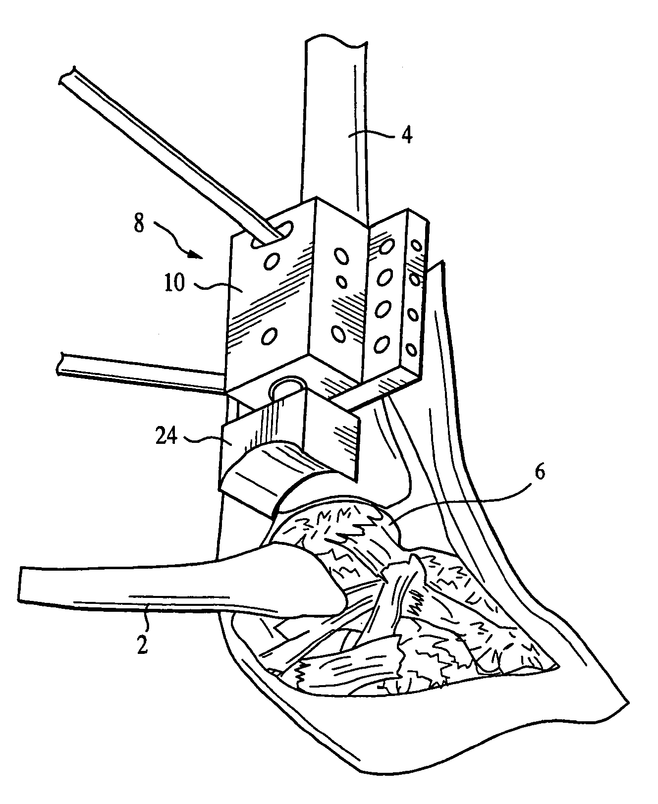
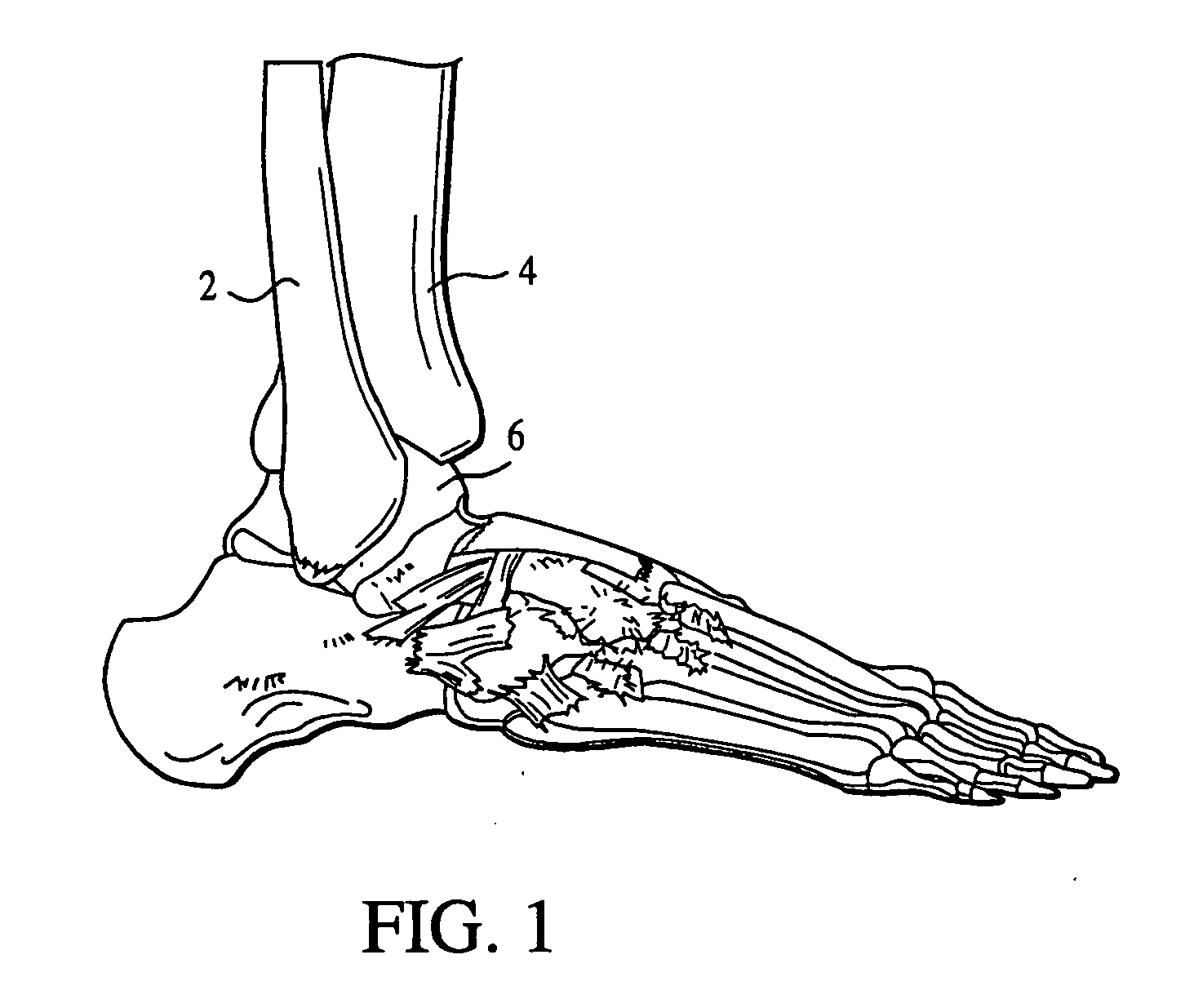
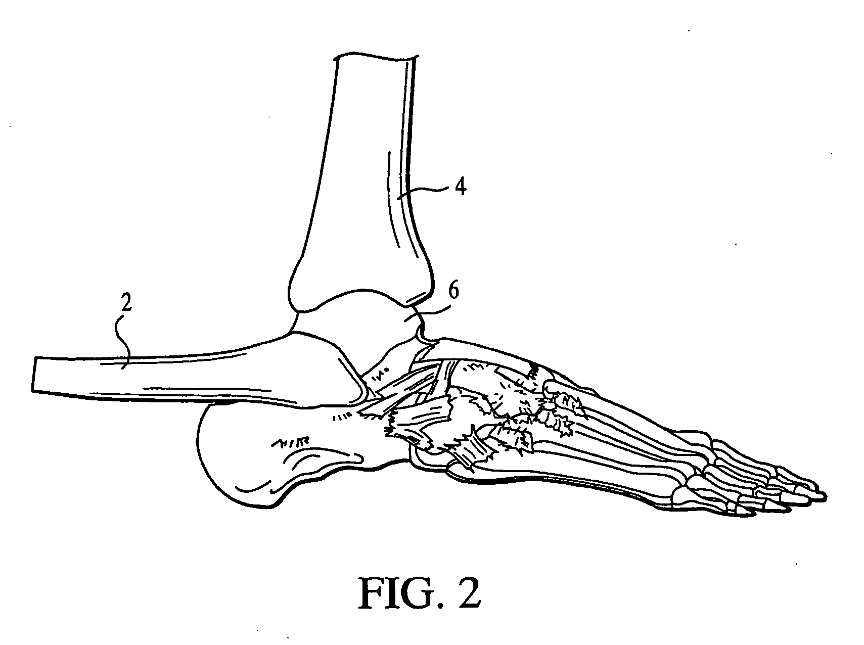
[0064] Referring now to the drawings wherein are shown preferred embodiments and wherein like reference numerals designate like elements throughout, there is shown in FIG. 1 a lateral, elevational view of a right, human foot that illustrates most of the foot bones and the lower ends of the lower leg bones. The present invention involves three of these bones: the fibula 2, the tibia 4 and the talus 6.

[0065] To gain lateral access...


PUM


Abstract

The ankle joint prosthesis adapted to involve the patient's distal tibia and talus has, according to the present invention, tibial, talar and mobile or semi-constrained bearing components that are laterally to medially implanted in the patient. The tibial component's top surface has convex curvature in its anterior to posterior plane and is configured so as to approximate and match with the curvature of a prepared portion of the distal tibia; its bottom surface being approximately flat. The talar component's top surface has saddle-shaped, convex curvature in its anterior to posterior plane, it's bottom surface has concave curvature and is configured so as to approximate and match with the curvature of a prepared portion of the talus. The mobile or semi-constrained bearing components have embodiments that comprise a wide variety of geometric shapes. A method for implanting such a prosthesis is also disclosed.

Description

CROSS-REFERENCE TO RELATED APPLICATIONS [0001] This application is a division of U.S. patent application Ser. No. 10 / 185,006, entitled “Ankle Joint Prosthesis and Its method of Implantation,” filed Jun. 27, 2002 by Lew C. Schon, Christopher Chiodo, Brent G. parks, Steven Herbst and Johnny Lau. The teachings of this prior application are incorporated herein by reference to the extent that they do not conflict with the teaching herein.BACKGROUND OF THE INVENTION [0002] 1. Field of the Invention [0003] This invention relates to ankle prostheses and the surgical procedures for implanting such prostheses. [0004] 2. Description of Prior Art [0005] For many years there has been considerable interest and activity with respect to ankle joint replacements, in which the degenerative articular surfaces are removed and replaced with an artificial joint called a prosthesis, as a viable approach to the treatment of diseased or injured ankle joints. [0006] Fusion has long been an alternative to ank...

Claims


Application Information

Patent Timeline
Patent Type & Authority Applications(United States)
IPC IPC(8): A61B17/15A61F2/00A61F2/30A61F2/42A61F2/46
CPCA61B17/15A61F2310/00029A61F2/4202A61F2002/30301A61F2002/30518A61F2002/30604A61F2002/30616A61F2002/30879A61F2002/30892A61F2002/30968A61F2002/4205A61F2002/4207A61F2002/4631A61F2220/0025A61F2230/0095A61F2310/00023A61F2/30767
Inventor SCHON, LEW C.PARKS, BRENT G.CHIODO, CHRISTOPHERHERBST, STEVENLAU, JOHNNY
Owner SCHON LEW C
Why Eureka
Try Eureka