Concrete placement vehicle control system and method

a technology for controlling systems and concrete, applied in the field of concrete placement vehicles, can solve the problems of loss of efficiency, difficulty for operators to easily control both systems, and inability of human operators to continuously and effectively control and monitor the concrete mixing and delivery system

Active Publication Date: 2005-01-06
OSHKOSH CORPORATION
View PDF99 Cites 122 Cited by
  • Summary
  • Abstract
  • Description
  • Claims
  • Application Information

AI Technical Summary

Benefits of technology

[0011] One embodiment of the invention relates to a concrete placement vehicle. The concrete placement vehicle includes a concrete mixing and placement system, at least one vehicle sensor configured to monitor a characteristic of the concrete placement vehicle and at least one concrete system sensor configured to monitor a characteristic of the system for mixing and placing concrete. The vehicle further includes a control system configured to control the operation of the concrete placement vehicle and the concrete mixing and placement system based on inputs received from the at least one vehicle sensor and the at least one concrete system sensor.
[0012] Another embodiment of the invention relates to a concrete placement system. The concrete placement system comprises a plurality of components for mixing and placing concrete including at least a first component and a second component, each component including an operational state. The system further includes a control system configured to determine the operational state of a first component and to control the first component based on an operational state of the second component.
[0013] Another embodiment of the invention relates to a concrete placement vehicle. The concrete placement vehicle comprises a concrete mixing and placement system comprises a mixing motor mounted to the concrete placement vehicle and configured to rotate a concrete mixing drum, a concrete delivery chute configured to be controlled by at least one actuator, and a power distribution and control system. The power distribution and control system further includes a power source, a power transmission link, a plurality of output devices and a plurality of input devices. The plurality of output devices includes a plurality of actuators capable of adjusting the position of the concrete delivery

Problems solved by technology

In some instances, the human operator is not able to continuously and effectively control and monitor the concrete mixing and delivery system while performing operations associated with the mixing and delivery process.
However, the drum rotation controls and the delivery system controls may be in separate locations making it difficult for the operator to easily control both systems.
Such an operation causes a loss in efficiency.
Yet further, while driving concrete from an

Method used


Image

  • Concrete placement vehicle control system and method
  • Concrete placement vehicle control system and method
  • Concrete placement vehicle control system and method

Examples


Embodiment Construction

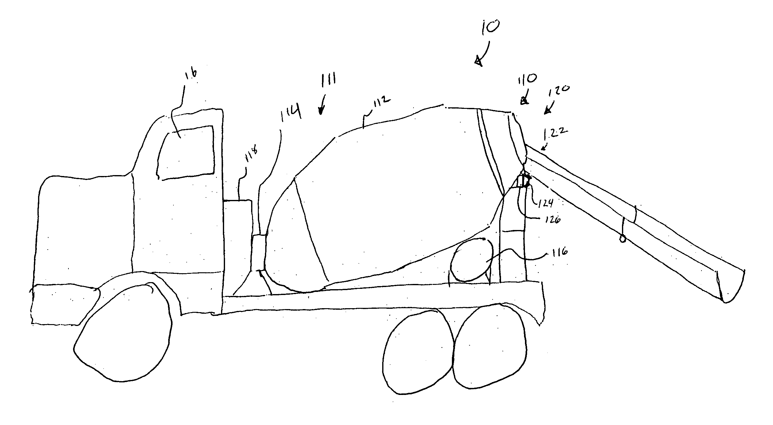
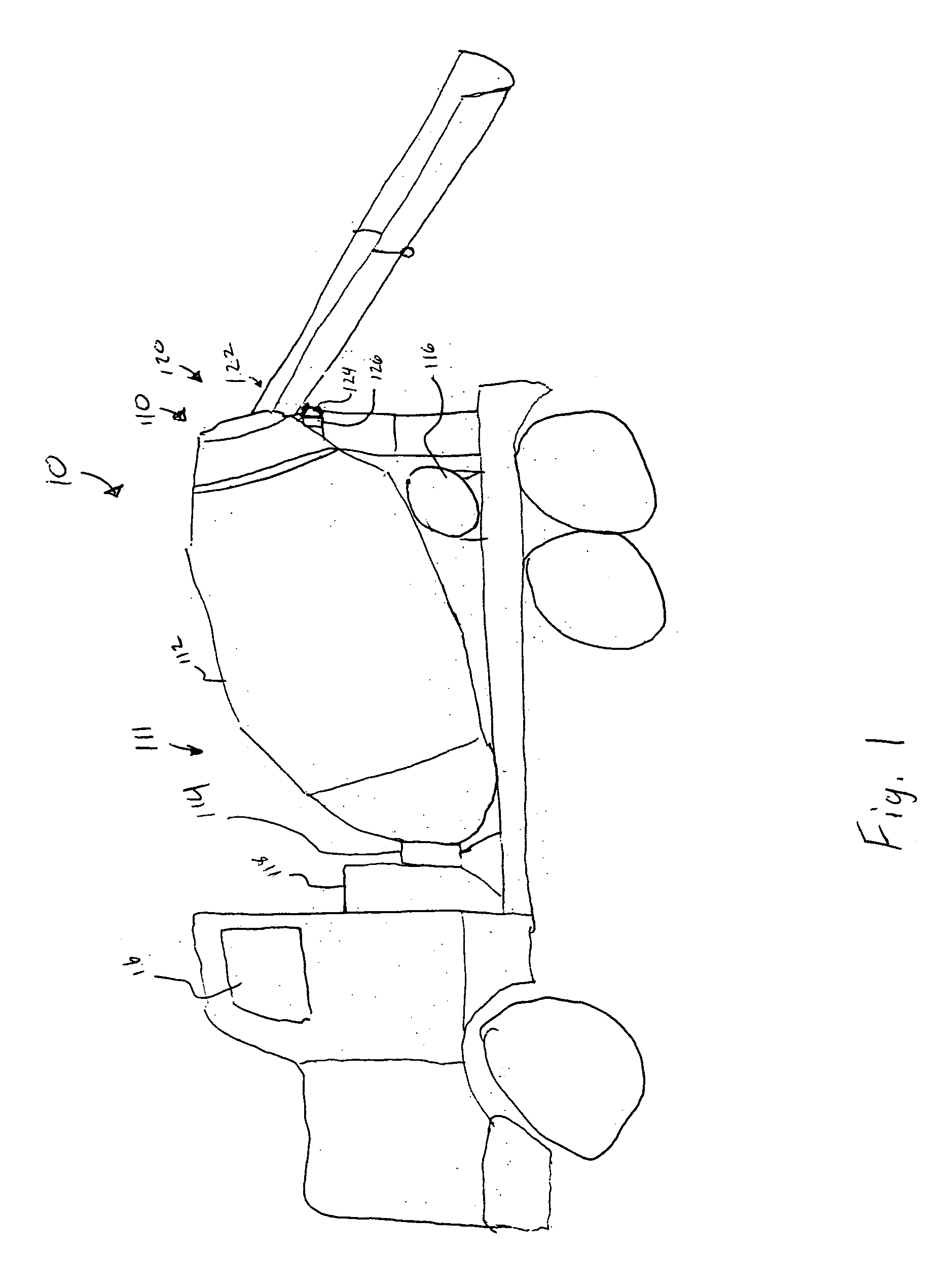
[0020] Referring to FIG. 1, an exemplary embodiment of a concrete placement vehicle 10 is illustrated. By way of overview, the concrete placement vehicle 10 generally includes a chassis, an engine, and a vehicle body mounted on the chassis, with the chassis and the vehicle body in combination including an operator compartment 16 capable of receiving a human operator. The operator compartment 16 further includes steering and throttle controls for receiving operator inputs to control the movement of the concrete placement vehicle 10 along a road. A concrete placement system 110 may be mounted to the concrete placement vehicle 10, and can be configured to transport and deliver a load of concrete. Delivery of a concrete load includes discharging the concrete load from the concrete placement system 110.

[0021] It should be understood that FIG. 1 merely illustrates one embodiment, and that the concrete placement vehicle 10 may have a variety of configurations. For example, in FIG. 1, the ...


PUM

PropertyMeasurementUnit
Speedaaaaaaaaaa
Contentaaaaaaaaaa
Elevationaaaaaaaaaa

Abstract

A concrete placement vehicle. The concrete placement vehicle includes a concrete mixing and placement system, at least one vehicle sensor configured to monitor a characteristic of the concrete placement vehicle and at least one concrete system sensor configured to monitor a characteristic of the system for mixing and placing concrete. The vehicle further includes a control system configured to control the operation of the concrete placement vehicle and the concrete mixing and placement system based on inputs received from the at least one vehicle sensor and the at least one concrete system sensor.

Description

CROSS-REFERENCE TO RELATED PATENT APPLICATIONS [0001] This application is a continuation-in-part of U.S. Ser. No. 09 / 927,946, filed Aug. 10, 2001, pending, which is a continuation-in-part of U.S. Ser. No. 09 / 384,393, filed Aug. 27, 1999, now U.S. Pat. No. 6,421,593, which is a continuation-in-part of U.S. Ser. No. 09 / 364,690, filed Jul. 30, 1999, abandoned, each of which is hereby expressly incorporated by reference. This application also claims priority to U.S. Patent Application. No. 10 / 326,862, filed Dec. 19, 2002, which claims priority to U.S. Prov. No. 60 / 342,292, filed Dec. 21, 2001, each of which is also hereby expressly incorporated by reference. This application further claims priority to U.S. Prov. No. 60 / 491,411, filed Jul. 31, 2003, which is hereby expressly incorporated by reference.BACKGROUND OF THE INVENTION [0002] The present invention relates generally to the field of concrete placement vehicles. More specifically, the present invention relates to concrete placement...

Claims


Application Information

Patent Timeline
IPC IPC(8): A62C27/00B60L3/12B60L50/15B60R16/02B60R16/03B65F3/04G07C5/08G08G1/123
CPCA62C27/00B28C5/4206B28C5/468B28C7/02B60R16/0315G08G1/20B65F3/045G07C5/008G07C5/08G07C5/085B65F3/043
Inventor PILLAR, DUANE R.WOOLMAN, WILLIAM M.
Owner OSHKOSH CORPORATION
Why Eureka
Try Eureka