
Apparatus and method for identifying ammunition

a technology for identification and ammunition, applied in the field of identification of ammunition, can solve the problems of ballistic fingerprinting methods, difficulty in certain methods used to manufacture components of firearms, and inability to identify ammunition

Inactive Publication Date: 2005-01-13
AMMUNITION CODING SYST
View PDF20 Cites 26 Cited by
  • Summary
  • Abstract
  • Description
  • Claims
  • Application Information

AI Technical Summary

Benefits of technology

[0010] The present invention is generally directed to an apparatus and methods for the identification of ammunition, and more specifically, to the application of an identifier to ammunition. In a first aspect, the invention includes an identifiable ammunition cartridge for a firearm having a bullet having a first identification surface, a casing that retains the bullet, the casing having a second identification surface, and an identifying code positioned on at least one of the first and the second identification surfaces. In another aspect of the invention, a method for identifying an ammunition article having at least one component includes selecting a first

Problems solved by technology

Despite the obvious advantages afforded by ballistic fingerprinting methods, drawbacks nevertheless exist.
Further, even if test cartridge information exists for a firearm, certain methods used to manufacture components of the firearm may present difficulties when attempting to identify a firearm by ballistic fingerprinting.
Still other problems present exist with present ballistic fingerprinting methods.
In such cases, traceability is also lost since there is generally no requirement to document these operations in a ballistic fingerprinting program.
Finally, the traceability of a firearm may also be lost by transferring ownership of the firearm to others through a series of undocumented personal transactions, so that the chain of ownership is lost.
Moreover, modification of the firearm by altering selected portions of the firearm would be ineffective in defeating an ammunition marking system.
Still further, ammunition marking could not, in general, be defeated by undocumented firearms sales, since the documentation is associated with the ammunition rather than the firearm.
The single identifier, however, may be rendered unreadable by deformation of the bullet, thus defeating subsequent attempts to identify the bullet.
Moreover, the single identifier is limited to the expression of relatively few numbers.
Consequently, if various bits within the binary array are rendered unreadable by deformation of the bullet, or by other means, subsequent identification of the ammunition component may not be possible.
In addition, the binary array may not be deciphered by persons not having specialized training directed to reading the contents of the binary array.
Accordingly, the ability of law enforcement agencies to read the contents of the array and to readily identify the ammunition component is impeded.

Method used


Image

  • Apparatus and method for identifying ammunition
  • Apparatus and method for identifying ammunition
  • Apparatus and method for identifying ammunition

Examples


Embodiment Construction

[0016] The present invention is generally directed to the identification of ammunition, and more specifically, to the application of an identifier to ammunition. Many of the specific details of certain embodiments of the invention are set forth in the following description and in FIGS. 1 to 4 to provide a thorough understanding of such embodiments. One skilled in the art will understand, however, that the present invention may be practiced without several of the details described in the following description. Moreover, in the description that follows, it is understood that the figures related to the various embodiments are not to be interpreted as conveying any specific or relative physical dimension. Instead, it is understood that specific or relative dimensions related to the embodiments, if stated, are not to be considered limiting unless the claims expressly state otherwise.

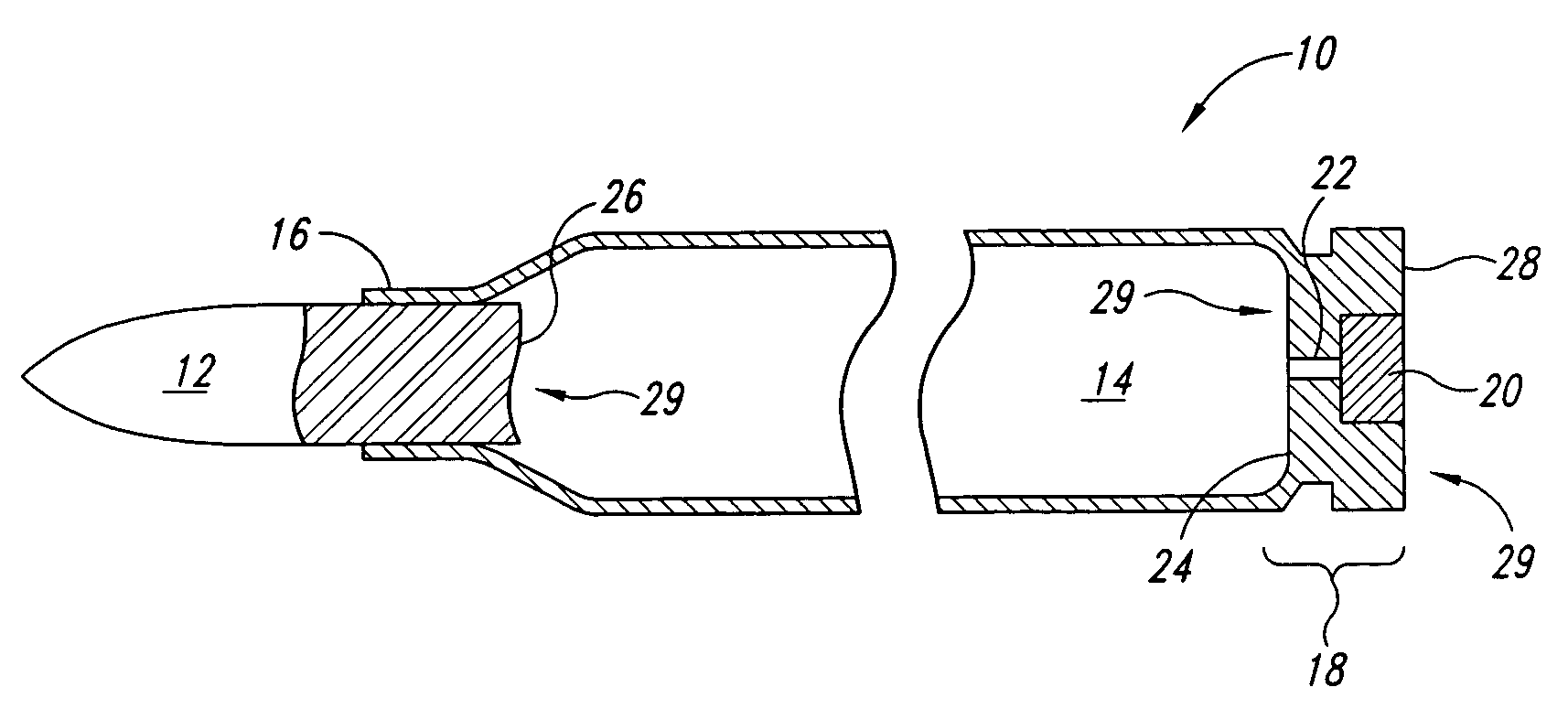
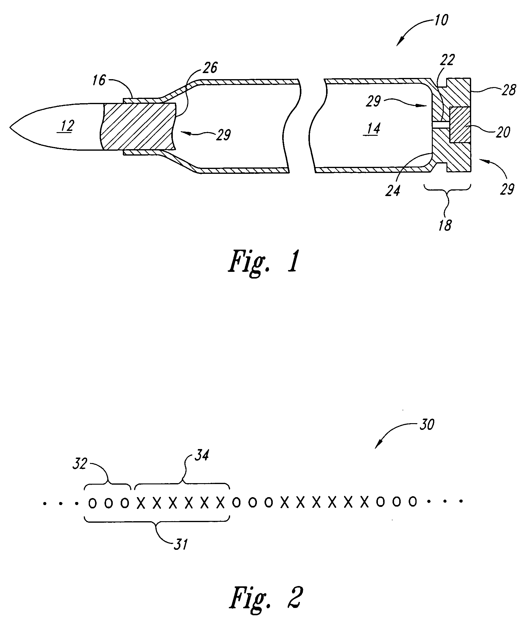
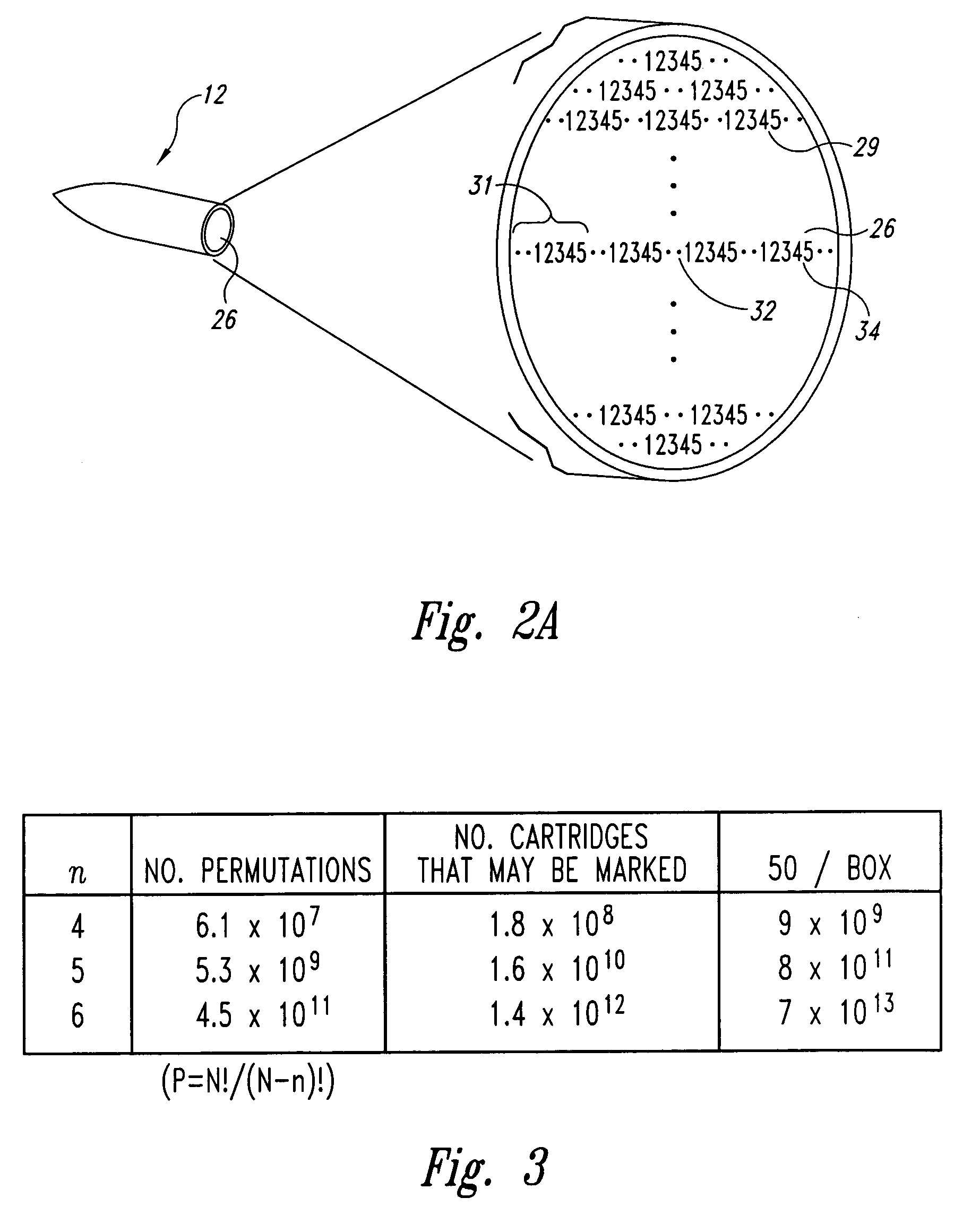
[0017]FIG. 1 is a partial cross-sectional view of a marked cartridge 10 according to an embodiment of the...


PUM


Abstract

The present invention is directed to identifying ammunition. In one embodiment, an identifiable ammunition cartridge includes a bullet having a first identification surface, a casing having a second identification surface, and an identifying code positioned on at least one of the first and the second identification surfaces. In another embodiment, a method for identifying ammunition includes selecting a first code portion and a second code portion, and combining the first code portion with the second code portion to form an identifier that may be applied to the ammunition. In still another embodiment, a method for tracking ammunition having an identifier includes storing the identifier and a corresponding identity of a first custodian in a data storage system, transferring the ammunition to a second custodian, associating the ammunition identifier with an identity of the second custodian, and storing the identity corresponding to the second custodian in the data storage system.

Description

TECHNICAL FIELD [0001] The present invention relates generally to the identification of ammunition, and more specifically, to the application of an identifying mark to ammunition. BACKGROUND OF THE INVENTION [0002] It has long been recognized that firearms form an identifiable series of marks, or striations on a projectile as it is discharged from the firearm. Since the striations generally result from minor differences that ordinarily arise during the manufacture of the firearm, the striations are generally unique, so that detectable differences exist even for firearms contemporaneously produced by the same manufacturer. As a result, forensic ballistic investigations often use these unique striation patterns to establish an association between a recovered projectile, such as a bullet, and a firearm. [0003] Various methods have been proposed that employ the striations formed on the projectile as the basis for an identification system for firearms. In one method, generally referred t...

Claims


Application Information

Patent Timeline
IPC IPC(8): F42B5/02F42B35/00
CPCF42B5/02F42B35/00F42B5/025
Inventor MACE, STEVEFORD, RUSSELL H.
Owner AMMUNITION CODING SYST
Learn More