Filler device

Inactive Publication Date: 2005-01-13
TOYODA GOSEI CO LTD
View PDF2 Cites 18 Cited by
  • Summary
  • Abstract
  • Description
  • Claims
  • Application Information

AI Technical Summary

Benefits of technology

[0035] As described above, the invention provides a filler

Problems solved by technology

Although this inlet pipe is advantageous in its lightweight and flexibility for arrangement, the bellows part can result in a high flow resistance in feeding the fuel, disturbing a smooth filling operation.
However, flexibility of the pipe is decreased by providing the flat portion partially formed on the bellows part and the arrangement of the pipe becomes more limit

Method used


Image

  • Filler device
  • Filler device
  • Filler device

Examples


first embodiment

[0044] First Embodiment

[0045] The first embodiment of the invention is described below.

[0046] (1) Schematic Construction of Filler Device 10

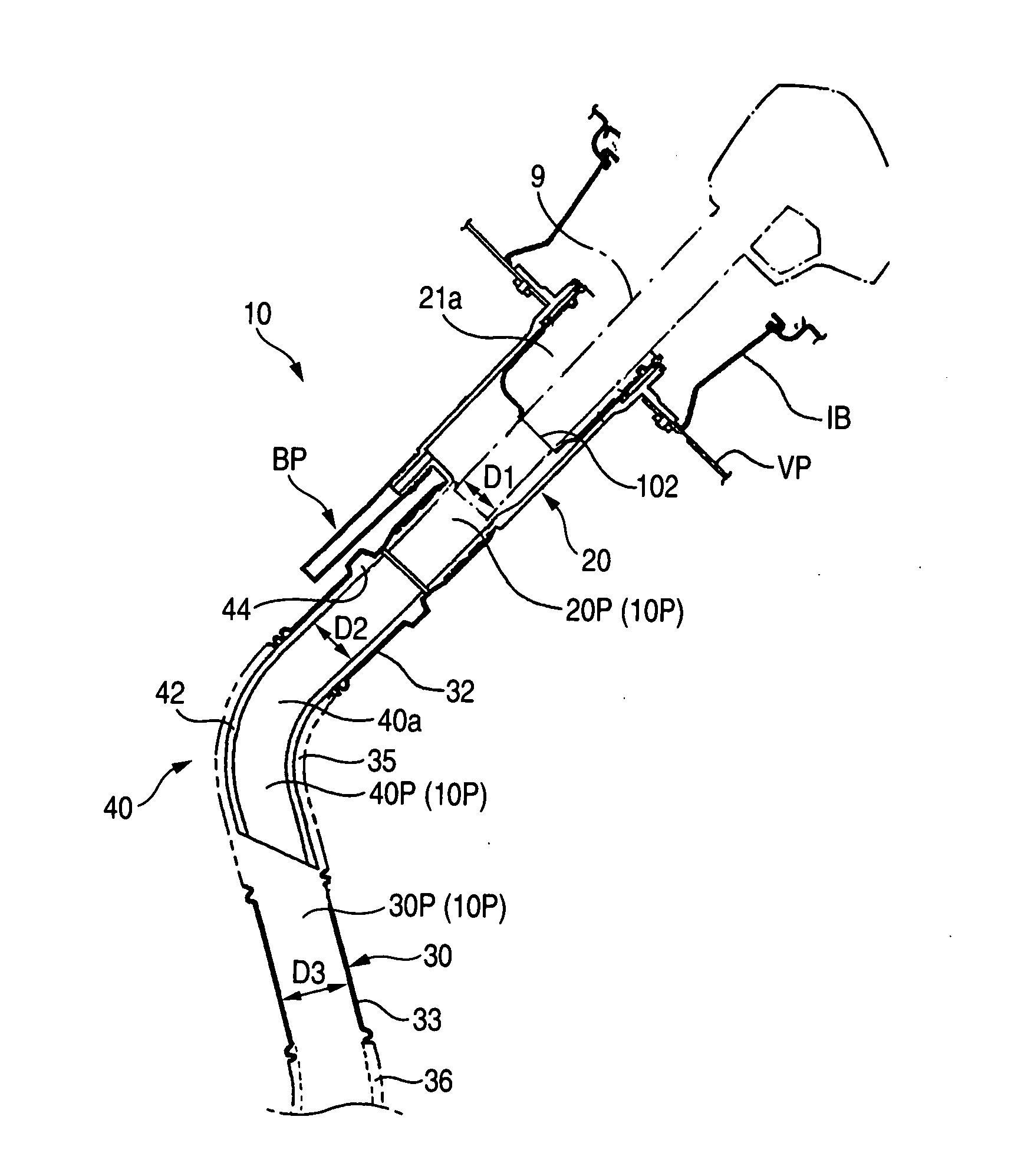
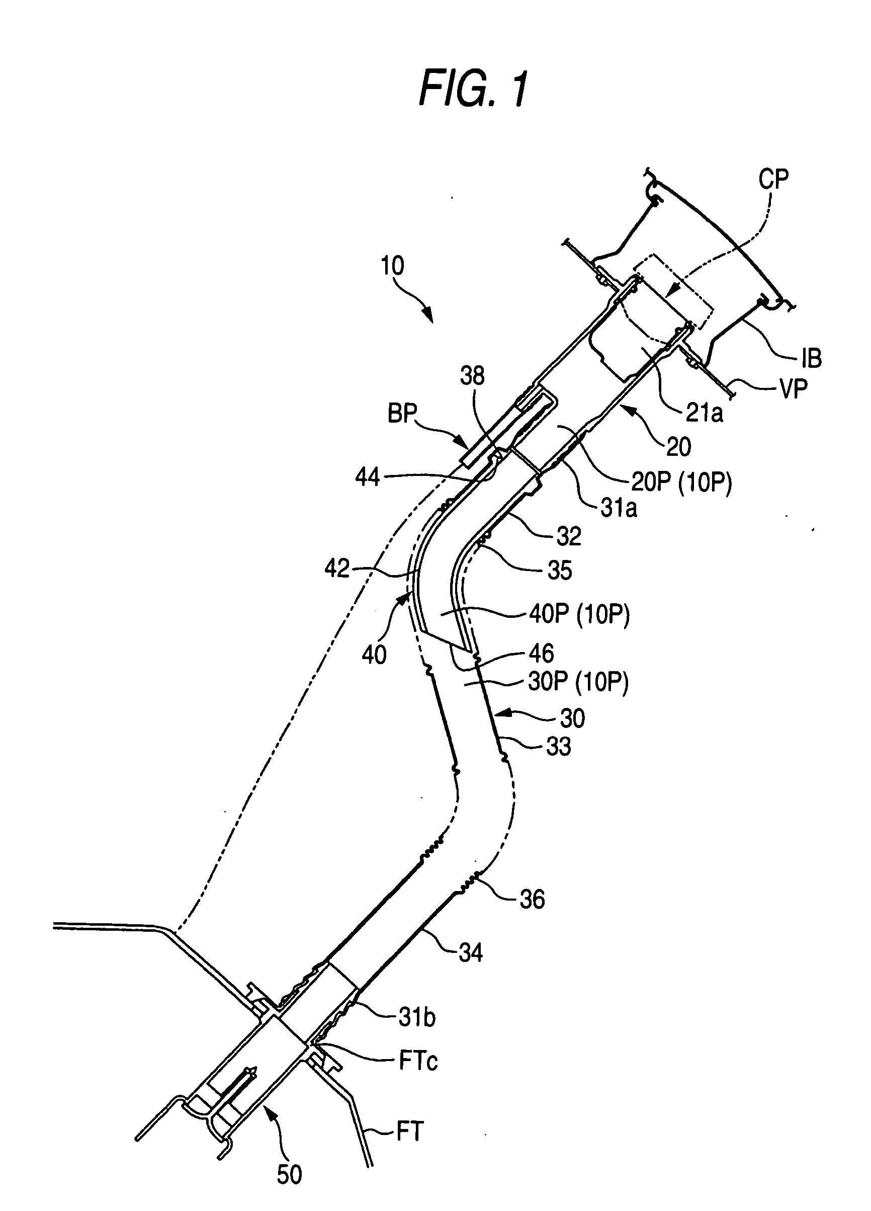
[0047]FIG. 1 is a schematic view showing a filler device according to the first embodiment of the invention. As shown in FIG. 1, the filler device 10 is provided to introduce a fuel fed by a fuel gun (not-shown) from an inlet box IB to a fuel tank FT. The filler device 10 is provided with a filler neck 20, a connection pipe 30 connecting the filler neck 20 to the fuel tank FT, an inner tube 40 inserted into the connection pipe 30, a check valve 50 for preventing liquid fuel or fuel gas from being emitted to outside due to a back-flow of the fuel, a fuel cap CP, and a breather pipe BP for aerating the fuel tank FT to the outside thereof during the filling operation. In other words, the inlet box IB is mounted on a vehicle body panel VP of an automobile, and the filler neck 20 is attached to the inlet box IB. The connection pipe 30 is connected t...

second embodiment

[0083] Second Embodiment

[0084] The second embodiment of the filler device of the invention will be described below. FIG. 7 is a longitudinal sectional view showing the filler device of the second embodiment, and FIG. 8 is an enlarged view showing the upper part of the filer device of FIG. 7. As shown in these figures, the filer device 110 includes a filler neck 120 and a connection pipe 130.

[0085] The filler neck 120 is made of polyethylene (PE) and is formed by blow forming. The filler neck 120 is provided with a neck body 121, a breather connection portion 123 and pipe connection portion 140.

[0086] The neck body 121 has a shape like a cup, so that an opening is formed on an upper side of the neck body 121. On the upper end of the neck body 121 is projected inside the inlet box (not-shown). A pouring inlet 121a is opened at the upper end of the neck body 121. An attachment metal 124 is inserted and fitted on an inner circumferential side of the pouring inlet. The attachment metal...


PUM

PropertyMeasurementUnit
Fractionaaaaaaaaaa
Fractionaaaaaaaaaa
Fractionaaaaaaaaaa

Abstract

A filler device comprising: a filler neck including a pouring inlet through which a fuel is injected and a neck connection portion; a connection pipe including a pipe connection end to which the neck connection portion is connected and a bellows part which is curved along a filling passage to a fuel tank; wherein the fuel injected through the pouring inlet is fed into the fuel tank through a filling passage, the connection pipe is provided with a pipe-side engaging portion on a back side of the pipe connection portion, the filler device further includes an inner tube including a tube body formed of a flexible elastomer material and inserted into the connection pipe, and a tube-side engaging portion projecting from an outer circumference at an end of the tube body, the inner tube is configured so that the tube body covers an inner wall of the bellows part and that the tube-side engaging portion is engaged with the pipe-side engaging portion, when the inner tube is inserted into the connection pipe, reaching to the back side of the pipe connection end.

Description

[0001] The present application is based on Japanese Patent Applications No. 2003-191851 and No. 2004-5609, the entire contents of which are incorporated herein by reference. BACKGROUND OF THE INVENTION [0002] 1. Field of the Invention [0003] The present invention relates to a filler device or filler pipe for guiding fuel into a fuel tank from a fuel gun. [0004] 2. Related Art [0005] The filler device couples an inside of an inlet box and an internal space of the fuel tank so as to communicate therebetween. An upstream end of the filler device is projected in the inlet box. A pouring inlet is formed on the upstream end of the filler device. The fuel provided from the fuel gun is injected into the fuel tank through an inside of the filler device. [0006] As such the filler devices, a resin inlet pipe on which a bellows part is formed is conventionally known. Although this inlet pipe is advantageous in its lightweight and flexibility for arrangement, the bellows part can result in a hig...

Claims


Application Information

Patent Timeline
IPC IPC(8): B60K15/04
CPCB60K15/04
Inventor MIURA, NATSUSHIYASUDA, ZENICHIANDO, MASAHIROHORI, TOMOKAZU
Owner TOYODA GOSEI CO LTD
Why Eureka
Try Eureka