Filler pipe
a filler pipe and pipe body technology, applied in the direction of liquid handling, packaging goods, transportation and packaging, etc., can solve the problems of reducing the flexibility of the pipe, and affecting the smooth filling operation
- Summary
- Abstract
- Description
- Claims
- Application Information
AI Technical Summary
Benefits of technology
Problems solved by technology
Method used
Image
Examples
first embodiment
[0044]The first embodiment of the invention is described below.
[0045](1) Schematic construction of filler pipe (device) 10
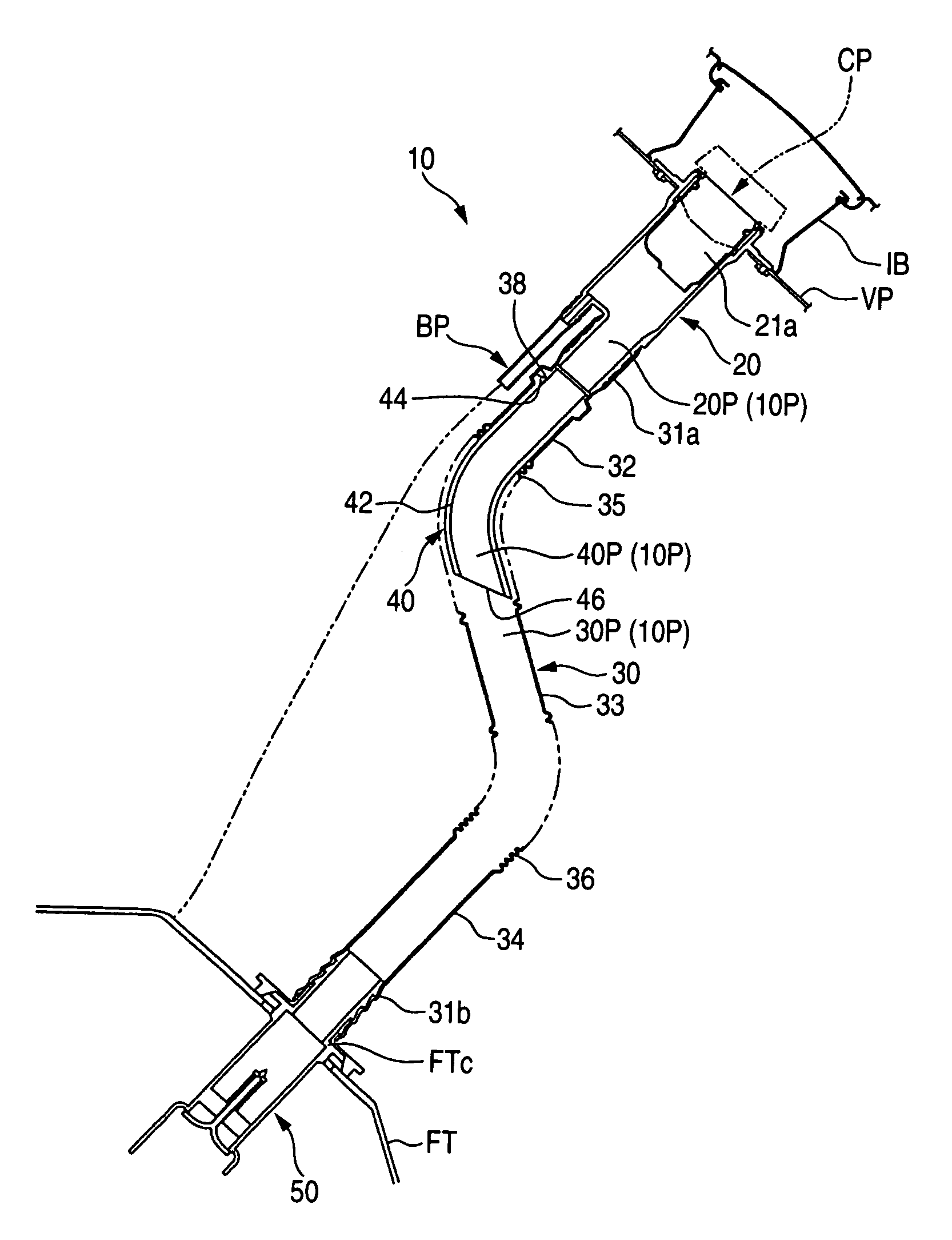
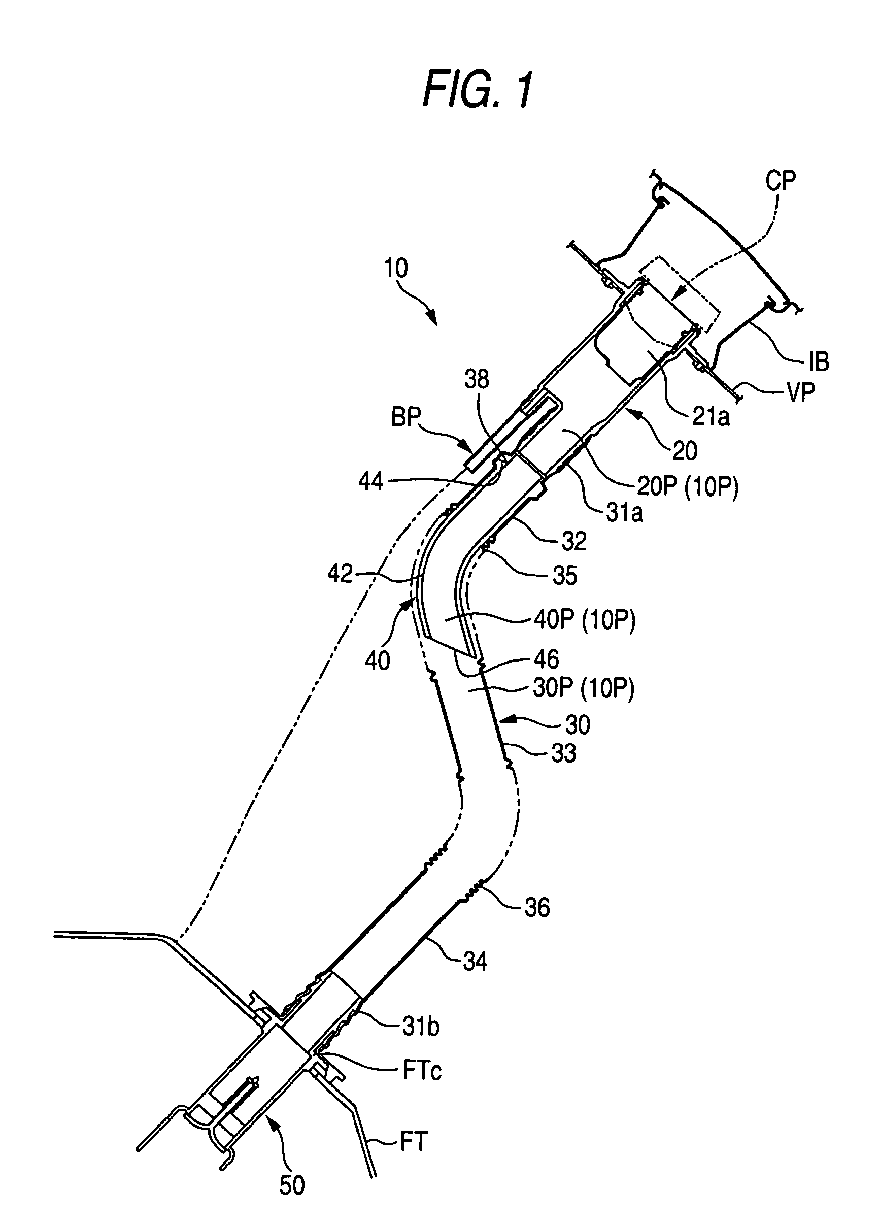
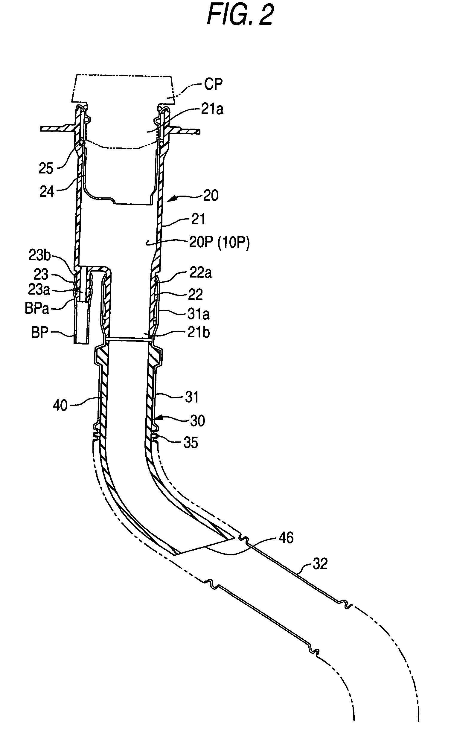
[0046]FIG. 1 is a schematic view showing a filler device according to the first embodiment of the invention. As shown in FIG. 1, the filler device 10 is provided to introduce a fuel fed by a fuel gun (not-shown) from an inlet box IB to a fuel tank FT. The filler device 10 is provided with a filler neck 20, a connection pipe 30 connecting the filler neck 20 to the fuel tank FT, an inner tube 40 inserted into the connection pipe 30, a check valve 50 for preventing liquid fuel or fuel gas from being emitted to outside due to a back-flow of the fuel, a fuel cap CP, and a breather pipe BP for aerating the fuel tank FT to the outside thereof during the filling operation. In other words, the inlet box IB is mounted on a vehicle body panel VP of an automobile, and the filler neck 20 is attached to the inlet box IB. The connection pipe 30 is connected to the fuel tank FT ...
second embodiment
[0082]The second embodiment of the filler device of the invention will be described below. FIG. 7 is a longitudinal sectional view showing the filler device of the second embodiment, and FIG. 8 is an enlarged view showing the upper part of the filer device of FIG. 7. As shown in these figures, the filer device 110 includes a filler neck 120 and a connection pipe 130.
[0083]The filler neck 120 is made of polyethylene (PE) and is formed by blow forming. The filler neck 120 is provided with a neck body 121, a breather connection portion 123 and pipe connection portion 140.
[0084]The neck body 121 has a shape like a cup, so that an opening is formed on an upper side of the neck body 121. On the upper end of the neck body 121 is projected inside the inlet box (not-shown). A pouring inlet 121a is opened at the upper end of the neck body 121. An attachment metal 124 is inserted and fitted on an inner circumferential side of the pouring inlet. The attachment metal 124 also has a shape like a ...
PUM
| Property | Measurement | Unit |
|---|---|---|
| outer diameter D1 | aaaaa | aaaaa |
| inner diameter D2 | aaaaa | aaaaa |
| inner diameter | aaaaa | aaaaa |
Abstract
Description
Claims
Application Information
 - R&D
- Intellectual Property
- Life Sciences
- Materials
- Tech Scout
- Unparalleled Data Quality
- Higher Quality Content
- 60% Fewer Hallucinations
Browse by: Latest US Patents, China's latest patents, Technical Efficacy Thesaurus, Application Domain, Technology Topic, Popular Technical Reports.
© 2025 PatSnap. All rights reserved.Legal|Privacy policy|Modern Slavery Act Transparency Statement|Sitemap|About US| Contact US: help@patsnap.com


