
Digital RF bridge

Inactive Publication Date: 2005-01-13
CRAM PAUL B
View PDF5 Cites 10 Cited by
  • Summary
  • Abstract
  • Description
  • Claims
  • Application Information

AI Technical Summary

Benefits of technology

[0006] (a) That this method of measurement eliminates errors due to residual and stray capacitance
[0007] (b) That this method eliminates errors in eye readings.)

Problems solved by technology

(c) That repeatability is improved because of the unbalanced arrangement of parts.

Method used


Image

  • Digital RF bridge
  • Digital RF bridge
  • Digital RF bridge

Examples


Embodiment Construction

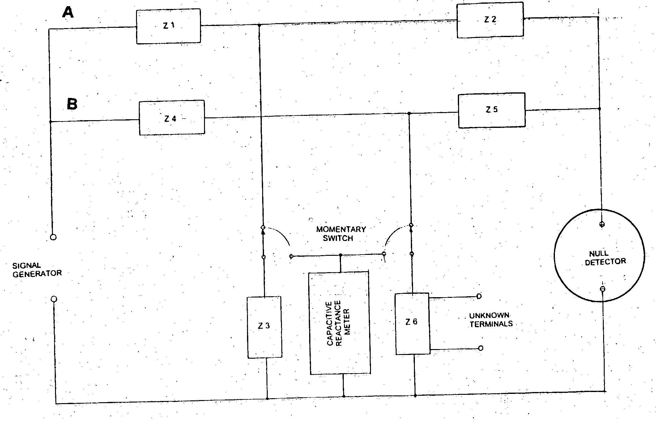
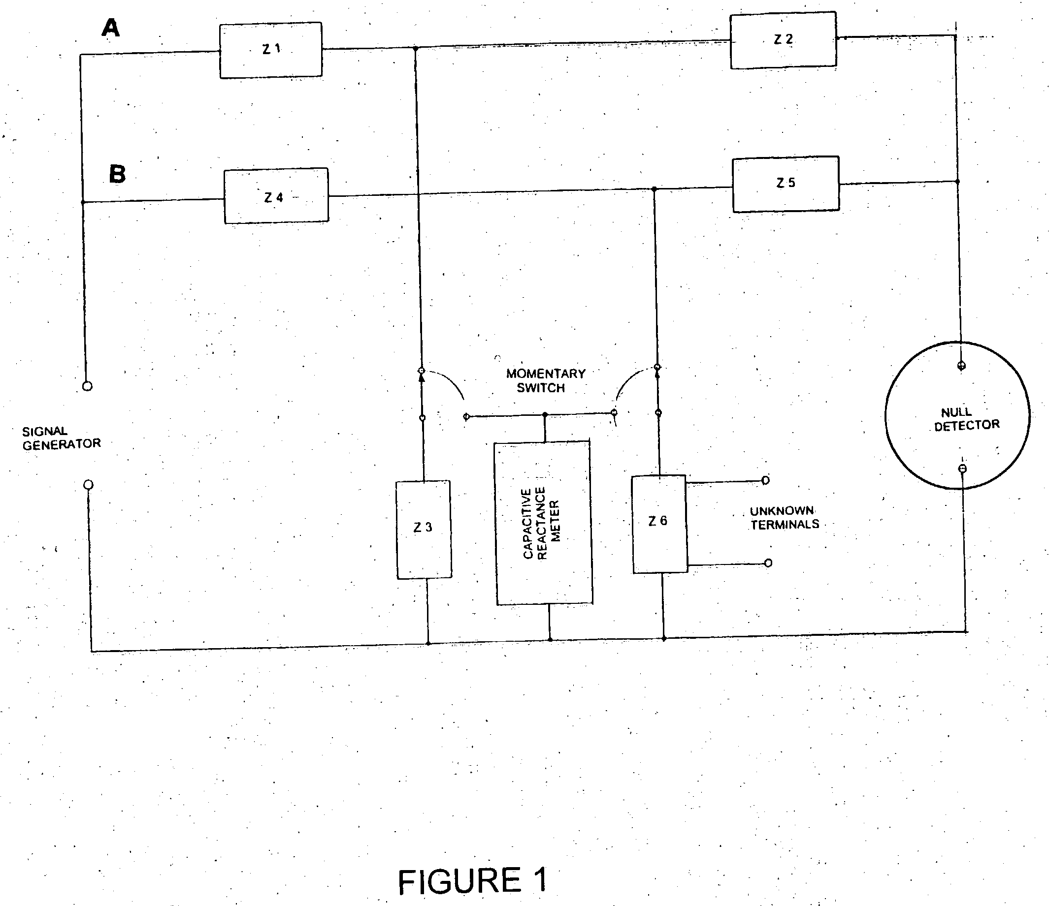
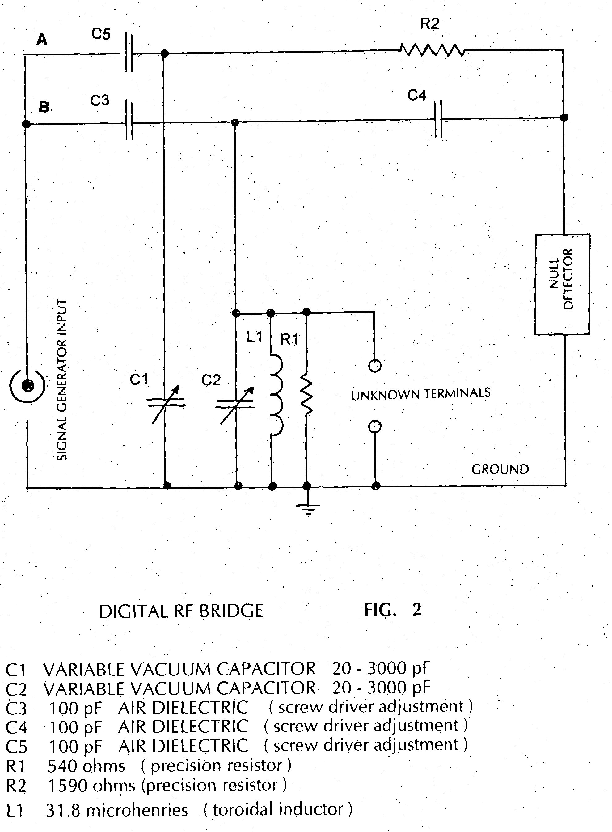
[0015] See FIG. 3. The Digital RF Bridge is an adaptation and variation of the conventional twin-t network. The T labeled A consists of resistance and capacitive reactance while the T labeled B has a shunt leg consisting of resistance, positive reactance and negative reactance in a parallel combination across which the unknown terminals are connected. This unusual configuration allows measurements of both positive and negative reactance with the shunt leg of the B network and resistance only with the shunt leg of the A network. The schematic diagram labeled FIG. 2 shows that the variable capacitor C! forms the shunt leg of A network and the variable capacitor C2 forms part of the shunt leg of B network. Increments of reactance of these two variable capacitors are used in the calculations of parallel resistance and reactance components of the unknown impedance under measurement.

[0016] As a part of the Digital RF Bridge, there is an electronic device that sends information to the com...


PUM


Abstract

A bridge of a twin-T type may have been proposed before but not in the form and function of this DIGITAL RF BRIDGE. In the DETAILED DESCRIPTION and MATHEMATICS writings of this application I describe the DIGITAL RF BRIDGE and it's process as being unique. The computer used here will be of ordinary origin but equipped with the special software. The printer is common and standard The signal generator is common, same as used regularly in bridge measurement processes. The null detector will normally be constructed as a part of the main bridge unit, well shielded and tunable. The device for measuring capacity values of C1 and C2 will normally be constructed as part of the main bridge unit and will work with the computer software to derive capacity in picofarads The Digital RF Bridge is dependent upon the computer and it's software to execute it's functions and, likewise, the computer process is dependent upon the functions of the Bridge unit. In the absence of either one, the process cannot exist.

Description

BACKGROUND OF THE DIGITAL RF BRIDGE [0001] Especially in the broadcast industry, but not only in the broadcast industry, there has always been a need for an instrument capable of measuring reactance and resistance of components and antennas. Bridges presently manufactured for this use are fitted with multiple dials, each with calibration markings. Accuracy of these instruments depends upon settings of these dials. In this environment there is also a need for an RF Bridge that will measure higher impedance unknowns. Bridges that I have used for the past 50 years are not directly applicable to measurements of impedance that include a resistive component above 1000 ohms. [0002] I have developed a bridge that requires no eye readings of the dials and that will make these measurements with better accuracy, of higher impedance unknowns and with less trouble. The frequency range within which it will work is only dependent upon mechanical aspects, the physical characteristics of the compone...

Claims


Application Information

Patent Timeline
Patent Type & Authority Applications(United States)
IPC IPC(8): G01R17/02G01R17/10G01R27/26
CPCG01R17/10G01R17/02
Inventor CRAM, PAUL B.
Owner CRAM PAUL B
Learn More