Method for adjusting a scanning module
- Summary
- Abstract
- Description
- Claims
- Application Information
AI Technical Summary
Benefits of technology
Problems solved by technology
Method used
Image

Examples
first embodiment
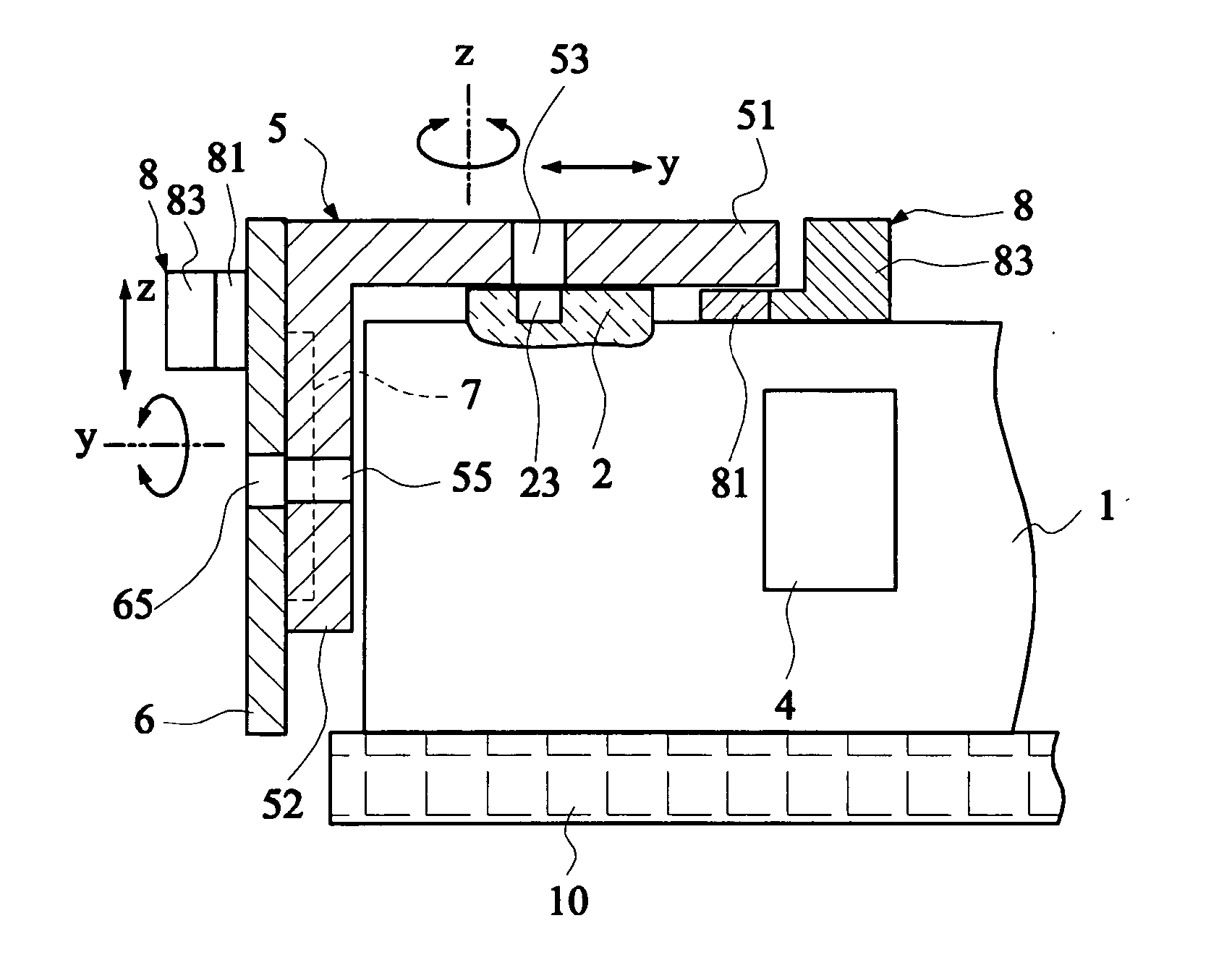
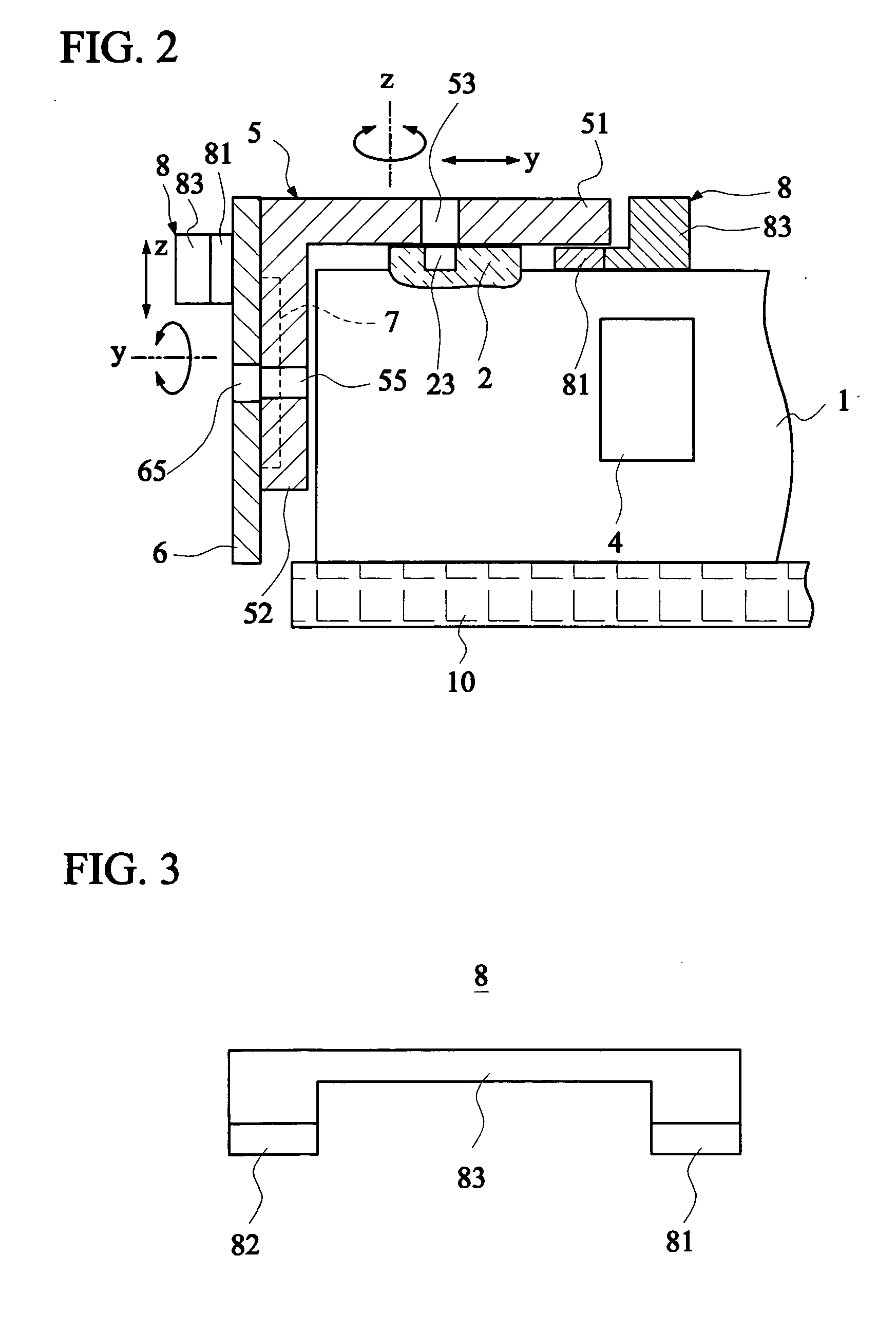
[0026]FIG. 2 is a schematic illustration showing a method for adjusting a scanning module according to the invention. FIG. 3 is a schematic illustration showing a magnetic assembly 8 of FIG. 2. Referring to FIG. 3, the magnetic assembly 8 includes two magnets 81 and 82 and a connecting portion 83 connecting the magnet 81 to the magnet 82. The method for adjusting the scanning module of the invention will be described with reference to FIGS. 2 and 3. First, the scanning module 1 is fixed to a table 10.
[0027] Then, a first mounting step, which is for mounting the first plate 51 of the adjustment assembly 5 onto the base 2 of the scanning module 1, and loosely fixing the adjustment assembly to the base with a first fixing force, is performed. It is to be noted that an image sensor 7 may be attached to the adjustment assembly 5 in advance, wherein the image sensor 7 may be attached to the adjustment assembly 5 by way of a circuit board 6 mentioned hereinafter. In this step, the adjuster...
fourth embodiment
[0039]FIG. 6 is a schematic illustration showing a method for adjusting a scanning module according to the invention. As shown in FIG. 6, the first and third fixing forces of this embodiment belong to the pushing forces, which are provided by the push rods 84 and 85, respectively. The pushing forces provided by the push rods 84 and 85 have the same effects as those of the magnetic force and have to be removed at last, and detailed descriptions thereof will be omitted.
fifth embodiment
[0040]FIG. 7 is a schematic illustration showing another method for adjusting a scanning module according to the invention. As shown in FIG. 7, the method of the invention also may be utilized to fix an image sensor 7 to a circuit board 6 having only a single plate. First, the scanning module 1 is fixed to the table 10. Then, the circuit board 6 is mounted onto a base 2 of the scanning module 1, and the circuit board 6 is loosely fixed to the base 2 of the scanning module 1 with a first fixing force. Next, the relative position between the circuit board 6 and the scanning module 1 is adjusted, and a first adjustment result is tested until the first adjustment result is accepted. Thereafter, the circuit board 6 is fixed to the base 2 of the scanning module 1 with a second fixing force. In this embodiment, the above-mentioned magnetic force, adhesive force or pushing force also may serve as the first fixing force.
PUM
 Abstract
Description
Claims
Application Information
 - R&D
- Intellectual Property
- Life Sciences
- Materials
- Tech Scout
- Unparalleled Data Quality
- Higher Quality Content
- 60% Fewer Hallucinations
Browse by: Latest US Patents, China's latest patents, Technical Efficacy Thesaurus, Application Domain, Technology Topic, Popular Technical Reports.
© 2025 PatSnap. All rights reserved.Legal|Privacy policy|Modern Slavery Act Transparency Statement|Sitemap|About US| Contact US: help@patsnap.com