Amplifying circuit, amplifying apparatus, and memory apparatus

a technology of amplifying circuit and amplifying apparatus, which is applied in the direction of differential amplifiers, digital storage, instruments, etc., can solve the problems of excessively low amplification factor, inability to carry out high-speed amplification, fear of electric power consumption, etc., to reduce time and power, improve efficiency, and improve the effect of amplifying circuit efficiency

Inactive Publication Date: 2005-01-13
SONY CORP
View PDF11 Cites 8 Cited by
  • Summary
  • Abstract
  • Description
  • Claims
  • Application Information

AI Technical Summary

Benefits of technology

[0028] Thus, if the potential difference between the input signals immediately after the start of amplifying operation is small, the differential type amplifying circuit is applied to carry out the amplifying operation, and if the potential difference of a certain degree is generated between the input signals, the latch type amplifying circuit is activated to carry out the amplifying operation. Consequently, it is possible to reduce the time and power which are necessary for the amplifying operation, and possible to simultaneously attain higher speed and lower electric power consumption of the amplifying circuit.
[0029] Consequently, it is possible to attain higher speed and lower electric power consumption of the memory device including this amplifying circuit, the various signal processing apparatuses, and the memory device, and is also possible to correspond to the requests of higher performance and lower electric power consumption of the respective electronic apparatuses of recent years.
[0030] Moreover, if the operation of the differential type amplifying circuit is stopped before the latch type amplifying circuit is operated, the potential of the signal amplified by the differential type amplifying circuit is reduced by discharge. Correspondingly, the time and labor which are necessary for the amplification is excessively consumed by this discharged amount. However, by stopping the operation of the differential type amplifying circuit after starting the operation of the latch type amplifying circuit, it is able to prevent the reduction in the signal amplified by the differential type amplifying circuit, and also is able to perform higher speed and lower electric power consumption of the amplifying circuit more and more.
[0031] That is, according to the present invention, after the switching circuit makes to operate the differential type amplifying circuit, the latch type amplifying circuit is operated, which enables the achievements of higher speed and lower electric power consumption of the amplifying circuit.
[0032] In particular, if it is designed to stop the operation of the differential type amplifying circuit after starting the operation of the latch type amplifying circuit, it is possible to prevent the drop in the signal amplified by the differential type amplifying circuit, and is possible to attain higher speed and lower electric power consumption of the amplifying circuit more and more.

Problems solved by technology

However, since a signal amplification factor is excessively low by the above mentioned one differential type amplifying circuit, it is recommended to increase the signal amplification factor.
To do so, it is necessary to connect plural stages of the differential type amplifying circuits in series, but this may bring about the fear of the increase in the electric power consumption.
However, in the range where the potential difference between latched input signals is minute, the input signals have to be gradually amplified, and this may bring about the fear that the amplification can not be carried out at high speed.
Accordingly, in the above-mentioned conventional amplifying circuits, it was impossible to attain both the higher speed and the lower electric power consumption.
Thus, it was impossible to satisfy the requirements of the higher performance and lower electric power consumption necessary for the respective electronic apparatuses of recent years.

Method used


Image

  • Amplifying circuit, amplifying apparatus, and memory apparatus
  • Amplifying circuit, amplifying apparatus, and memory apparatus
  • Amplifying circuit, amplifying apparatus, and memory apparatus

Examples


Embodiment Construction

[0040] The specific embodiments of the amplifying circuit according to the present invention will be described below with reference to the drawings. By the way, an amplifying circuit according to the present invention can be applied to a sensing amplifier of a memory device, and can be applied even to amplifying circuits of the other various signal processing apparatuses.

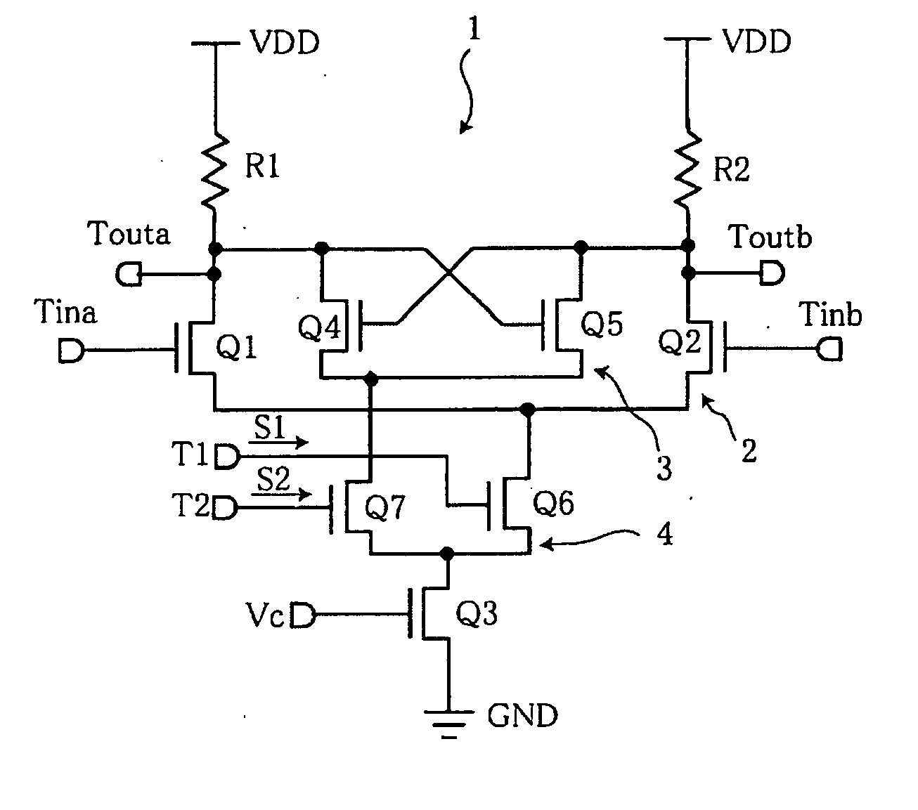
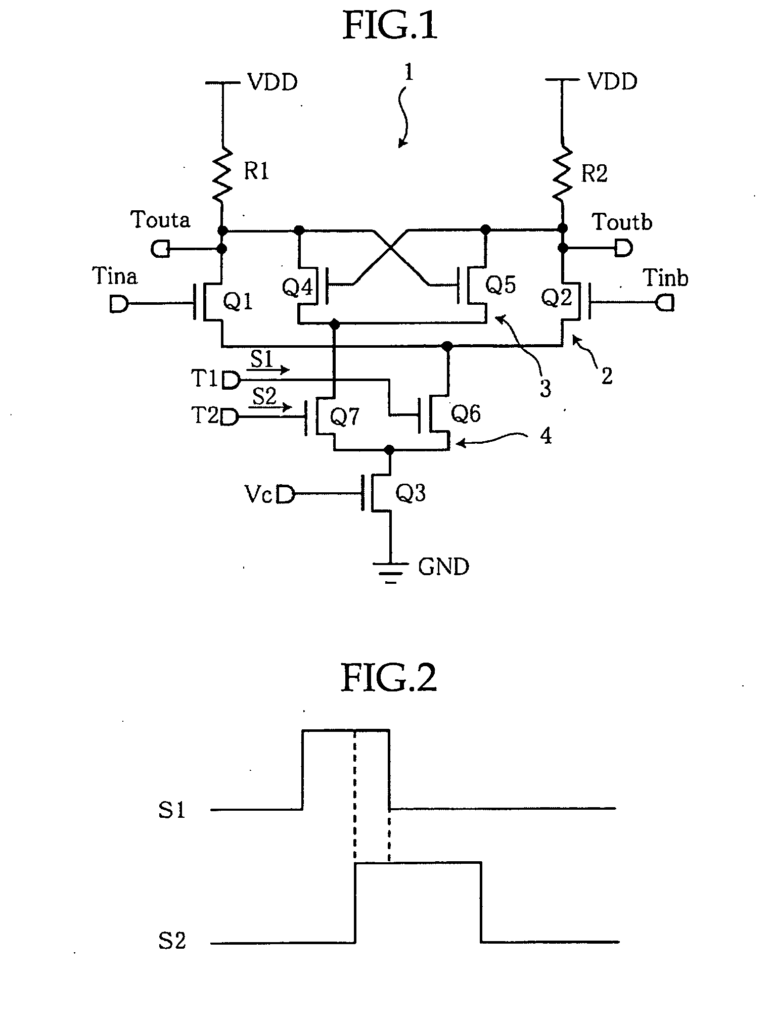
[0041] An amplifying circuit 1 according to the present invention is provided with a differential type amplifying circuit 2, a latch type amplifying circuit 3, and a switching circuit 4 for switching the operation between those two amplifying circuits 2, 3, as shown in FIG. 1.

[0042] The differential type amplifying circuit 2 is composed of N-channel MOS-type transistors (FETs) Q1, Q2 serving as a differential pair, a pair of resistors R1, R2 serving as a load, and an N-channel MOS-type transistor (FET) Q3 serving as a constant current source.

[0043] Specifically, in the differential type amplifying circuit 2, each...


PUM


Abstract

The present invention is proposed to attain the higher speed and lower electric power consumption in an amplifying circuit, wherein the amplifying circuit comprises a differential type amplifying circuit, a latch type amplifying circuit, and a switching circuit for switching the differential type amplifying circuit and the latch type amplifying circuit. In this configuration, the differential type amplifying circuit and the latch type amplifying circuit have a common load. Further in the present amplifying circuit, the switching circuit stops the operation of the differential type amplifying circuit after starting the operation of the latch type amplifying circuit.

Description

CROSS REFERENCE TO RELATED APPLICATION [0001] This application claims priority from Japanese Priority Document No. 2003-273646, filed on Jul. 11, 2003 with the Japanese Patent Office, which document is hereby incorporated by reference. BACKGROUND OF THE INVENTION [0002] 1. Field of the Invention [0003] The present invention relates to an amplifying circuit, amplifying apparatus, and a memory apparatus. [0004] 2. Description of Related Art [0005] Conventionally, amplifying circuits for amplifying signals are mostly used in various circuits built in many kinds of electronic apparatuses. In particular, in a memory apparatus having a larger storage capacity, a sensing amplifier serving as the amplifying circuit is connected to each of memory cells. [0006] As the above-mentioned amplifying circuit, a differential type amplifying circuit 101 having differentially connected two transistors Q101, Q102 as shown in FIG. 6, and also a latch type amplifying circuit 102 in which a latch is compo...

Claims


Application Information

Patent Timeline
Patent Type & Authority Applications(United States)
IPC IPC(8): G11C11/419G11C7/06G11C7/08G11C11/409H03F3/45
CPCG11C7/065G11C7/06G11C7/08
Inventor NAKASHIMA, KATSUYA
Owner SONY CORP
Why Eureka
Try Eureka