Optical recording medium, master for optical recording medium manufacture, recording and reproducing apparatus, and recording and reproducing method

Inactive Publication Date: 2005-01-13
SONY CORP
View PDF6 Cites 2 Cited by
  • Summary
  • Abstract
  • Description
  • Claims
  • Application Information

AI Technical Summary

Benefits of technology

[0028] In the invention, since the recording area is formed as total six tracks of the first to third grooves and the first to third lands between respective two of them, track density can be made into remarkably higher density. Further, since the first and second grooves are formed as deep grooves and the third

Problems solved by technology

Therefore, it has been difficult to make the track density into higher density equal to or more than twice the conventional one.
When the groove width and the land width are substantially the same, the push-pull signal provides a sufficient signal amount at the maximum, however, the signal amount of the CTS signal becomes insufficient, as shown in FIG. 1.
As described above, if t

Method used


Image

  • Optical recording medium, master for optical recording medium manufacture, recording and reproducing apparatus, and recording and reproducing method
  • Optical recording medium, master for optical recording medium manufacture, recording and reproducing apparatus, and recording and reproducing method
  • Optical recording medium, master for optical recording medium manufacture, recording and reproducing apparatus, and recording and reproducing method

Examples


Embodiment Construction

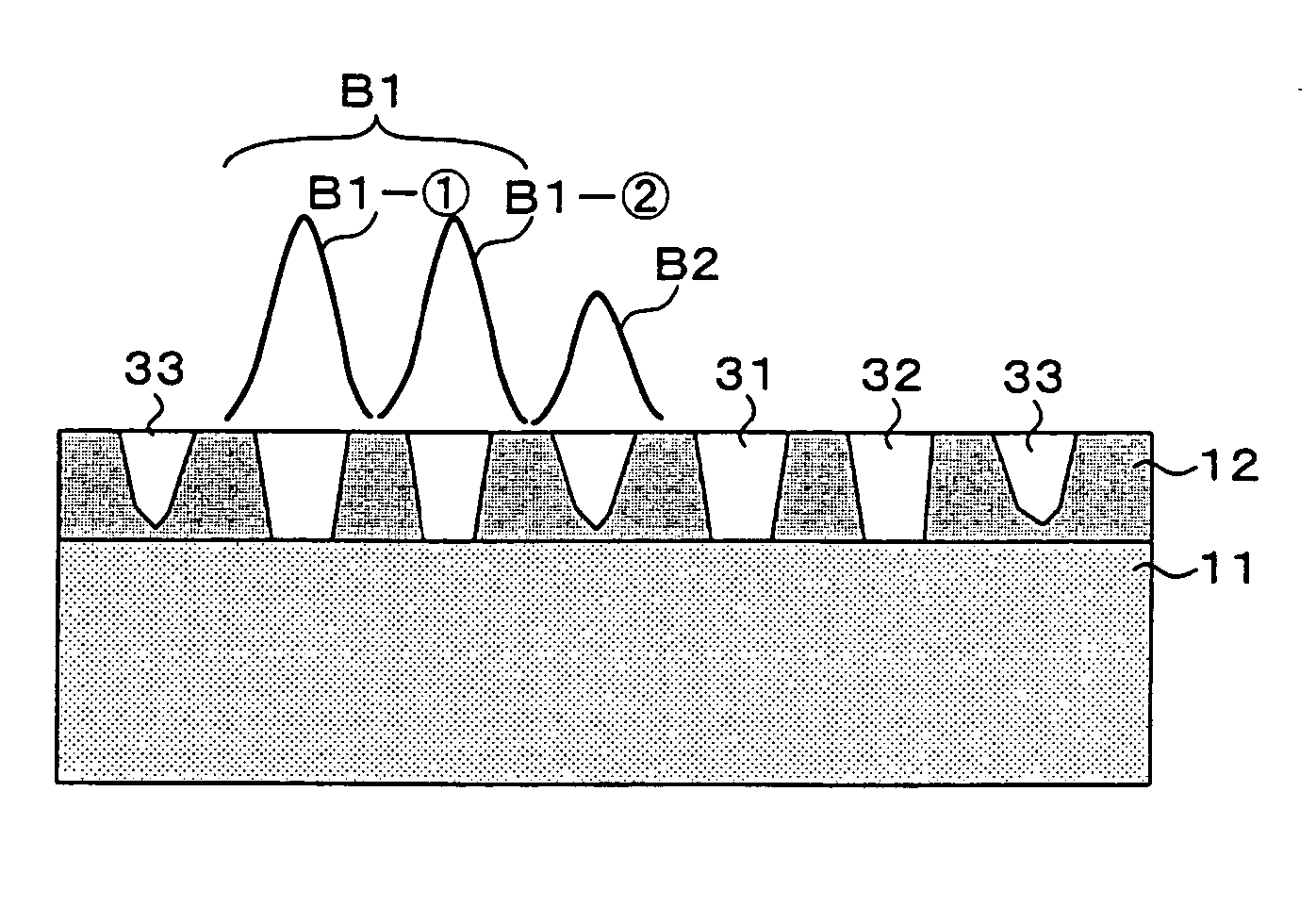
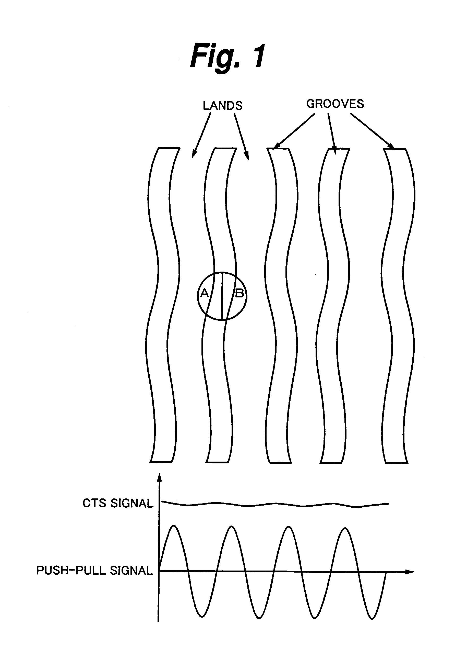
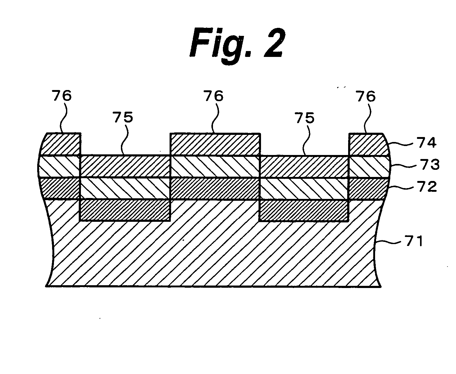
[0038] Hereinafter, embodiments of the invention will be described in detail by referring to the drawings. With respect to a magneto-optical disk to which the invention is applied, sectional views in which main parts thereof are enlarged are shown in FIGS. 3A and 3B. FIG. 3A shows a construction of the magneto-optical disk, and FIG. 3B shows an example of a specific recording track structure. FIGS. 4A to 4C are diagrams relating to a recording area of the magneto-optical disk. FIG. 4A is an enlarged view of a part of the recording area, FIG. 4B shows an output waveform of a CTS signal by a photo detector, and FIG. 4C is an output waveform of a push-pull signal by the photo detector.

[0039] The reference sign 1 in FIG. 3A denotes the magneto-optical disk. The magneto-optical disk 1 is formed in a disc shape, and recording and reproduction of data is performed by utilizing the magneto-optical effect. Further, the magneto-optical disk 1 includes a recording layer 3 on which magneto-opt...


PUM


Abstract

To make a magneto-optical disk to have higher track density and enable stable tracking servo to be performed thereon. On an magneto-optical disk, a first groove Gv1, a second groove Gv2, and a third groove Gv3 are formed so as to be adjacently arranged. The first groove Gv1 and the second groove Gv2 are deep grooves, and the third groove Gv3 is a shallow groove. Data is recorded on six recording tracks of these three grooves and three lands between respective grooves. A CTS signal is obtained by a sum signal (A+B+C+D) of a photo-detector 6, and a push-pull signal is obtained by a difference signal (A+D)−(B+C) of a photo-detector 8.

Description

BACKGROUND OF THE INVENTION [0001] 1. Field of the Invention [0002] The present invention relates to an optical recording medium having grooves formed along recording tracks and a master for optical recording medium manufacture used when manufacturing such optical recording medium. Further, the invention relates to a recording and reproducing apparatus and a recording and reproducing method for performing recording and / or reproduction processing on an optical recording medium having grooves formed along recording tracks. [0003] 2. Description of the Related Art [0004] As conventional recordable disk-shape recording media, an MD (Mini Disc), a CD (Compact Disc)-R (Recordable), a CD-RW (ReWritable), a DVD (Digital Versatile Disc or Digital Video Disc)+RW (ReWritable), a DVD-R (Recordable), a DVD-RW (ReWritable), etc. are proposed. For formats of these disk-shape recording media, a groove recording format for recording in grooves is adopted. [0005] For each format of an magneto-optical...

Claims


Application Information

Patent Timeline
IPC IPC(8): G11B7/007G11B7/09G11B7/26G11B11/105
CPCG11B7/00718G11B7/0903G11B7/0938G11B7/24076G11B11/10584G11B7/261G11B7/263G11B11/10578G11B7/24079A01G9/1438A01G9/242Y02P60/14
Inventor ENDOH, SOHMEI
Owner SONY CORP
Why Eureka
Try Eureka