Eureka AIR delivers breakthrough ideas for toughest innovation challenges, trusted by R&D personnel around the world.

Objective lens driving apparatus for an optical head

a driving apparatus and optical head technology, applied in the direction of mountings, instruments, data recording, etc., can solve the problems of difficult to obtain good recording and reproduction characteristics on the optical disk medium, and difficult to solve. achieve the effect of good recording and reproduction characteristics of information, without increasing the power consumption of the optical disk apparatus

Inactive Publication Date: 2005-01-20
NEC CORP
View PDF4 Cites 2 Cited by
  • Summary
  • Abstract
  • Description
  • Claims
  • Application Information

AI Technical Summary

Benefits of technology

[0013] It is an object of the present invention to provide an objective lens driving apparatus for an optical head which exerts a high thrust in a radial or tracking direction without increasing the power consumption of an optical disk apparatus to achieve good recording and reproduction characteristics of information.
[0014] It is another object of the present invention to provide an objective lens driving apparatus for an optical head which suppresses vibration by a rolling mode of a lens holder even when the objective lens is moved in a direction of an optical axis or in a focusing direction thereby to achieve good recording and reproduction characteristics of information.
[0015] It is a further object of the present invention to provide an objective lens driving apparatus for an optical head which can exert a high thrust in a direction of an optical axis.

Problems solved by technology

This, however, increases the power consumption of the optical disk apparatus.
Although it is possible to adopt the apparatus of the Patent Document 1 only if it is intended to reduce the power consumption, it is difficult to solve the following problem.
This displaces the central point of the electromagnetic forces generated by the tracking coils along the direction of the optical axis and gives rise to a problem that resonance by rolling that, when the tracking coils and hence the lens holder performs a tracking movement and a focusing movement, it performs tilting movements, which makes it difficult to obtain good recording and reproduction characteristics on an optical disk medium.

Method used


Image

  • Objective lens driving apparatus for an optical head
  • Objective lens driving apparatus for an optical head
  • Objective lens driving apparatus for an optical head

Examples


Embodiment Construction

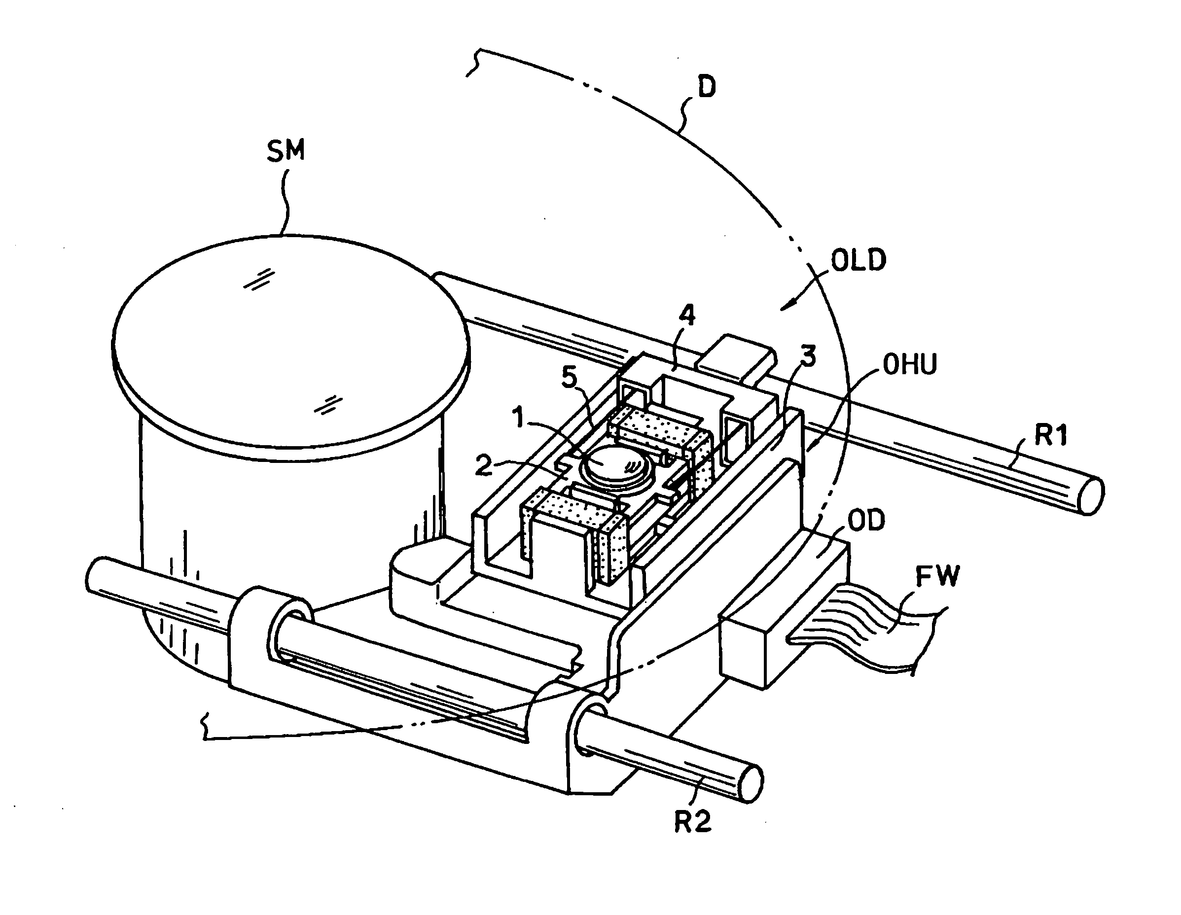
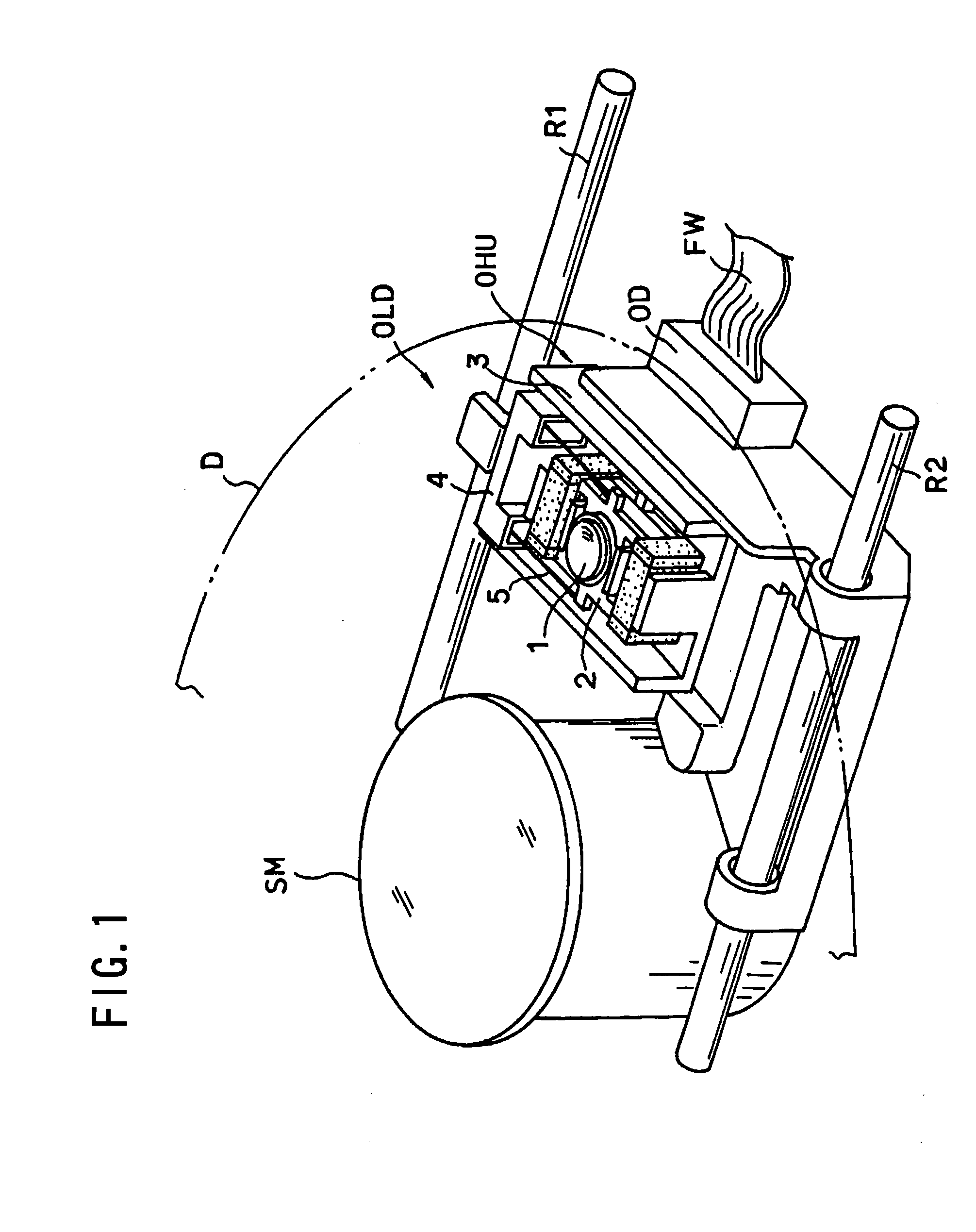
[0041] Referring to FIG. 1, there is shown an optical disk apparatus in which an objective lens driving apparatus to which the present invention is applied is incorporated. The optical disk apparatus includes a spindle motor SM for driving an optical disk medium D such as a CD indicated by an imaginary line to rotate at a high speed, and a pair of rails R1 and R2 extending in parallel along a radial direction of the spindle motor SM. An optical head unit OHU is supported on the rails R1 and R2 such that it can be moved back and forth in a radial direction of the optical disk medium D along the rails R1 and R2 by a driving mechanism not shown. An objective lens driving apparatus OLD to which the present invention is applied is carried on the optical head unit OHU, and also a light source section OD including a light emitting element such as a semiconductor laser and a light receiving element such as a light receiving diode is supported on the optical head unit OHU. A laser beam emitt...


PUM

PropertyMeasurementUnit
electric currentaaaaaaaaaa
electromagnetic forcesaaaaaaaaaa
polarityaaaaaaaaaa

Abstract

An objective lens driving apparatus for an optical head is disclosed which exerts a high thrust in focusing and radial directions with reduced power consumption and suppresses vibration by a rolling mode of a lens holder even when a focused position of an objective lens is shifted thereby to achieve a good reproduction characteristic. Each of a pair of magnets for forming magnetic fields necessary for causing a focusing coil and tracking coils to generate electromagnetic forces is magnetized so as to have three poles including a centrally located N pole and a pair of opposite side S poles in the radial or tracking direction. Each of the tracking coils is disposed such that the two opposite sides thereof in the radial direction are opposed separately to the N and S poles so that a thrust or electromagnetic force of a magnitude substantially equal to twice is generated in the radial direction. The permanent magnets have a length in the direction of the optical axis greater than that of the tracking coil so that the magnetic intensity is uniformed and the rolling mode of the objective lens is suppressed. The boundary portions of the three poles are positioned on the outer sides of yokes so that the thrust (or electromagnetic force for the focusing coil is increased.

Description

BACKGROUND OF THE INVENTION [0001] 1. Field of the Invention [0002] The present invention relates to an objective lens driving apparatus for driving an objective lens provided on an optical head for recording or reproducing information on or from an optical disk medium, and more particularly to saving of the power and suppression of resonance of an objective lens by a rolling mode in an object lens driving apparatus of the type described. [0003] 2. Description of the Related Art [0004] An optical disk apparatus which uses an optical disk medium such as a CD (Compact Disk) or a DVD (Digital Versatile Disk) usually includes an optical head for condensing a laser beam emitted from a laser light source such as a semiconductor laser on an information recording surface of an optical disk medium by means of an objective lens to record, reproduce and erase information on and from the information recording surface. In an optical disk apparatus of the type described, the track position on the...

Claims


Application Information

Patent Timeline
Patent Type & Authority Applications(United States)
IPC IPC(8): G11B7/00G02B7/04G11B7/085G11B7/09
CPCG11B7/08582G11B7/0935G11B7/0933G11B7/0932
Inventor FUJITA, MASAYUKI
Owner NEC CORP
Why Eureka
Eureka Blog
Learn More