High density fiber optic cable

a fiber optic cable, high-density technology, applied in the direction of optics, fibre mechanical structures, instruments, etc., can solve the problems of reducing the performance of optical fibers, and achieve the effect of preventing adhesion, preventing adhesion, and high optical fiber coun

Inactive Publication Date: 2005-01-13
CORNING OPTICAL COMM LLC
View PDF29 Cites 1 Cited by
  • Summary
  • Abstract
  • Description
  • Claims
  • Application Information

AI Technical Summary

Benefits of technology

[0014] A fiber optic cable is provided according to yet another aspect of the present invention that includes a central member, a plurality of non-jacketed bundles of optical fibers extending along the central member with each bundle of optical fibers including a plurality of optical fibers and a binder encircling the optical fibers to maintain the optical fibers in the bundle. The fiber optic cable of this embodiment also includes a cable jacket surrounding the bundles of optical fibers and a separation element for preventing adhesion between the bundles of optical fibers and the cable jacket without jacketing each bundle of optical fibers.
[0015] A fiber optic cable according to a further aspect of the present invention includes a plurality of non-jacketed bundles of optical fibers with each bundle including a plurality of optical fibers and a binder thread encircling the optical fibers to maintain the optical fibers in the bundle. The fiber optic cable of this embodiment also includes a separation layer surrounding the bundles of optical fibers and a cable jacket surrounding the separation layer. The separation layer prevents adhesion between the bundles of optical fibers and the cable jacket without having to separately jacket each bundle of optical fibers.
[0016] The fiber optic cable of the present invention therefore includes a relatively high count of optical fibers, while reducing the size or diameter of the fiber optic cable. In this regard, the fiber optic cable of the present invention preferably includes a plurality of bundles of optical fibers that are not separately jacketed, thereby permitting the diameter of the fiber optic cable to be reduced. However, the fiber optic cable of the present invention can include a binder, such as a binder thread, for maintaining the integrity of the respective bundles. Moreover, the fiber optic cable can include a separation element for preventing adhesion between the plurality of non-jacketed bundles of optical fibers and the cable jacket such that the optical fibers can move somewhat relative to the cable jacket as the fiber optic cable is bent or flexed such that the optical signals propagating along the optical fibers are not undesirably attenuated as a result of the flexure of the fiber optic cable.

Problems solved by technology

Unfortunately, the adherence of the tight buffered optical fibers 14 to the surrounding jacket 28 generally decreases the performance of the optical fibers.

Method used


Image

  • High density fiber optic cable
  • High density fiber optic cable
  • High density fiber optic cable

Examples


Embodiment Construction

[0025] The present invention now will be described more fully hereinafter with reference to the accompanying drawings, in which preferred embodiments of the invention are shown. This invention may, however, be embodied in many different forms and should not be construed as limited to the embodiments set forth herein; rather, these embodiments are provided so that this disclosure will be thorough and complete, and will fully convey the scope of the invention to those skilled in the art. Like numbers refer to like elements throughout.

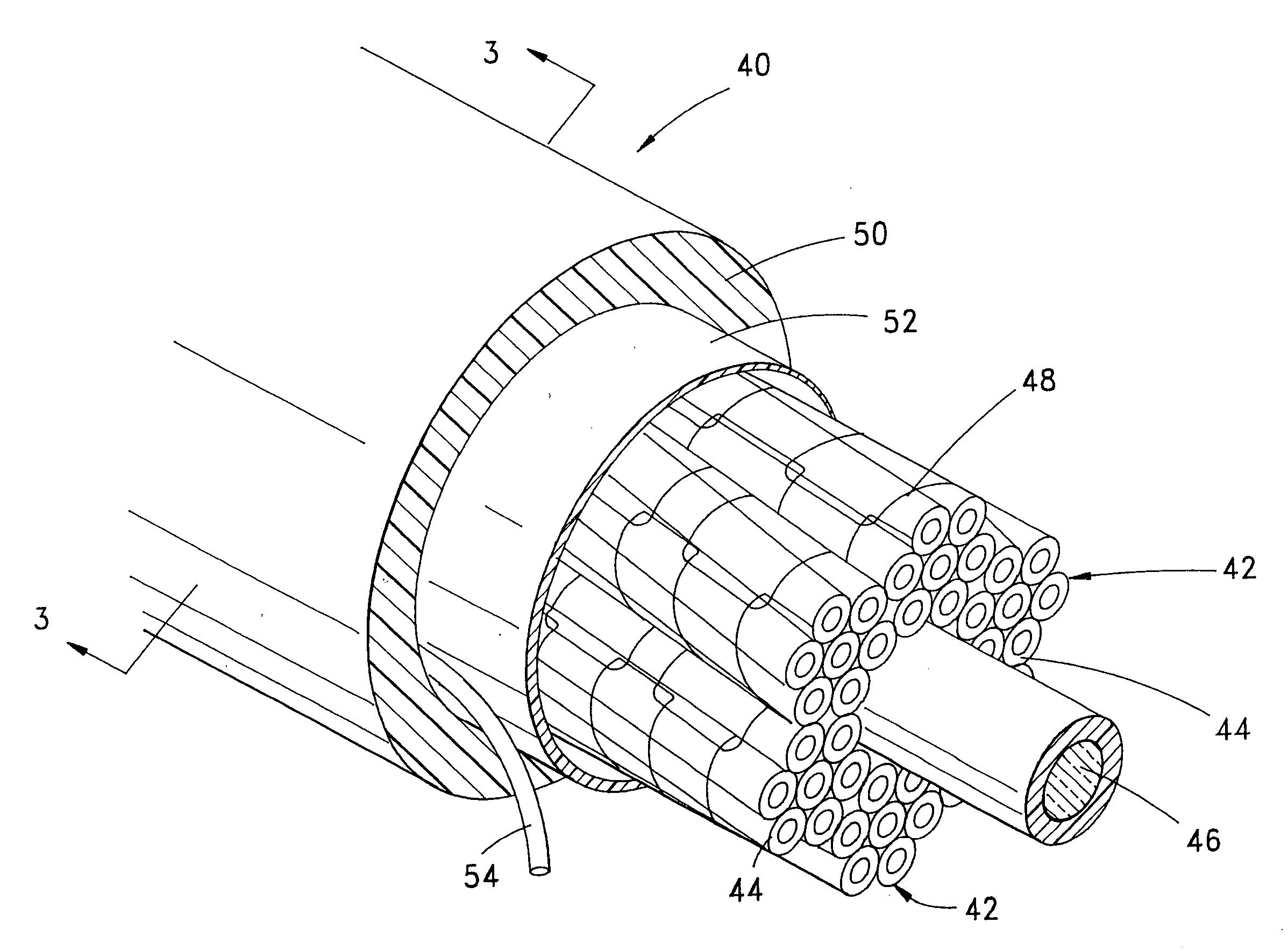
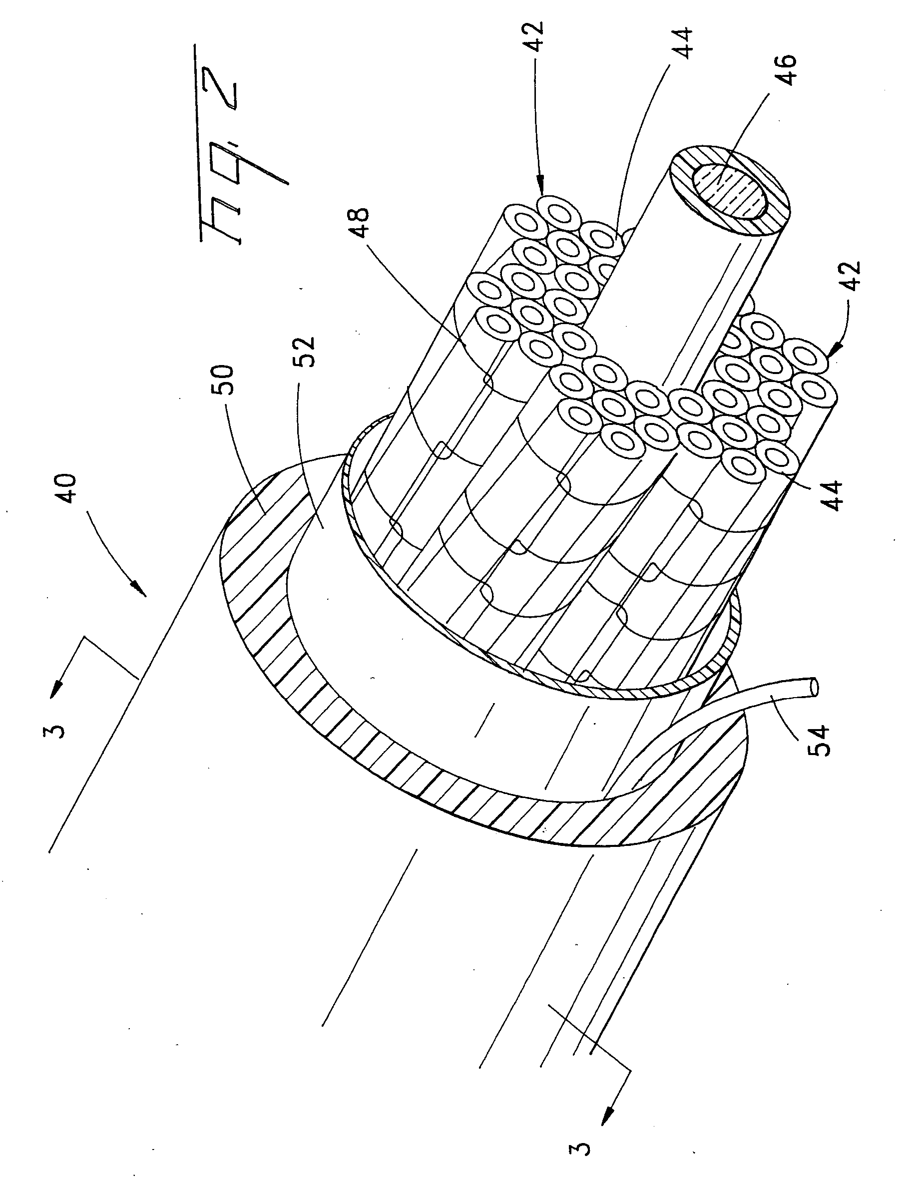
[0026] Referring now to FIG. 2, a fiber optic cable 40 according to one embodiment of the present invention is illustrated. Fiber optic cable 40 of the present invention can have other configurations as described below, although the fiber optic cable of FIG. 2 will be described in more detail hereinbelow for purposes of illustration. Fiber optic cable 40 includes a plurality of bundles 42 of optical fibers 44. Typically, fiber optic cable 40 also include...


PUM


Abstract

A fiber optic cable is provided that includes a plurality of lengthwise extending, non-jacketed bundles of optical fibers and a cable jacket surrounding the bundles of optical fibers. Each bundle of optical fibers may include a binder, such as a binder thread, for maintaining the integrity of the bundle. The binder may include, for example, a binder thread formed of an air entangled, textured, continuous multi-filament thread. The fiber optic cable may also include a separation element for preventing adhesion between the bundles of optical fibers and the cable jacket without having to separately jacket each bundle of optical fibers.

Description

FIELD OF THE INVENTION [0001] The present invention relates generally to fiber optic cables and, more particularly, to high density fiber optic cables. BACKGROUND OF THE INVENTION [0002] In many applications, it is desirable for a fiber optic cable to include a plurality of optical fibers. With the increased demand for optical communications, there has been a corresponding demand to increase the number of optical fibers, i.e., the fiber count, of a fiber optic cable. By increasing the fiber count of a fiber optic cable, a single fiber optic cable would be able to support additional optical communications channels. [0003] In order to increase the fiber count of fiber optic cables, unitized fiber optic cables have been developed. As shown in FIG. 1, a unitized fiber optic cable 10 includes a number of bundles 12 of optical fibers 14 that are stranded about a common central strength member 16. A unitized fiber optic cable 10 also includes a cable jacket 18 extruded about the bundles 12...

Claims


Application Information

Patent Timeline
Patent Type & Authority Applications(United States)
IPC IPC(8): G02B6/44
CPCG02B6/441
Inventor MCALPINE, WARREN W.HURLEY, WILLIAM C.WAGMAN, RICHARD S.BAUCOM, JAMES L.MCDOWELL, SCOTT A.
Owner CORNING OPTICAL COMM LLC
Why Eureka
Try Eureka