Inflatable compressor bleed valve system

a compressor and valve system technology, applied in the field of gas turbine engines, can solve problems such as heavy and complex arrangements

Inactive Publication Date: 2005-01-13
PRATT & WHITNEY CANADA CORP
View PDF19 Cites 72 Cited by
  • Summary
  • Abstract
  • Description
  • Claims
  • Application Information

AI Technical Summary

Benefits of technology

[0009] In accordance with a further general aspect of the present invention, there is provided a combination compressor bleed valve actuation and seal system for bleeding air from a gas turbine engine compressor, wherein the gas turbine engine compressor has at least one airbleed pas...

Problems solved by technology

This leads to heavy and complex arrangements.
Furthermore, each valve typically comprises a...

Method used


Image

  • Inflatable compressor bleed valve system
  • Inflatable compressor bleed valve system
  • Inflatable compressor bleed valve system

Examples


Embodiment Construction

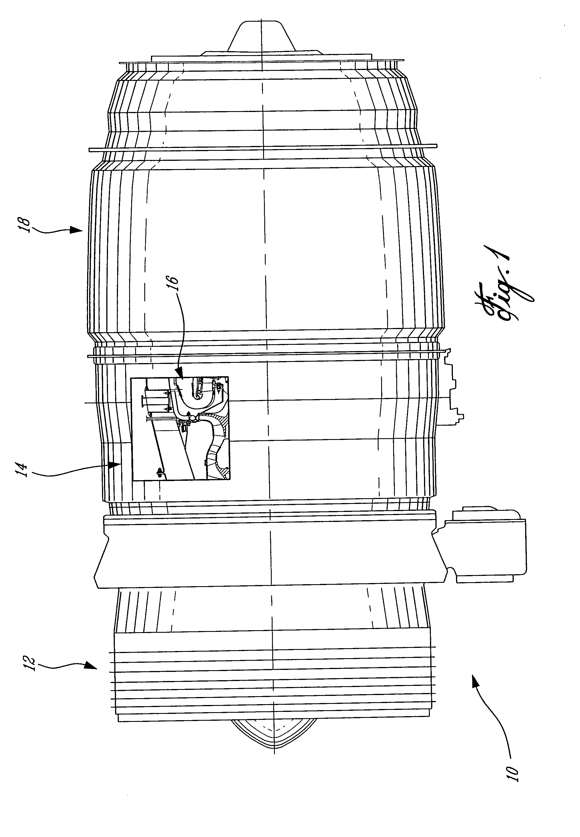
[0017]FIG. 1 illustrates a gas turbine engine 10 generally comprising in serial flow communication a fan 12 through which ambient air is propelled, a multistage compressor 14 for pressurizing the air, a combustor 16 in which the compressed air is mixed with fuel and ignited for generating an annular stream of hot combustion gases, and a turbine 18 for extracting energy from the combustion gases.

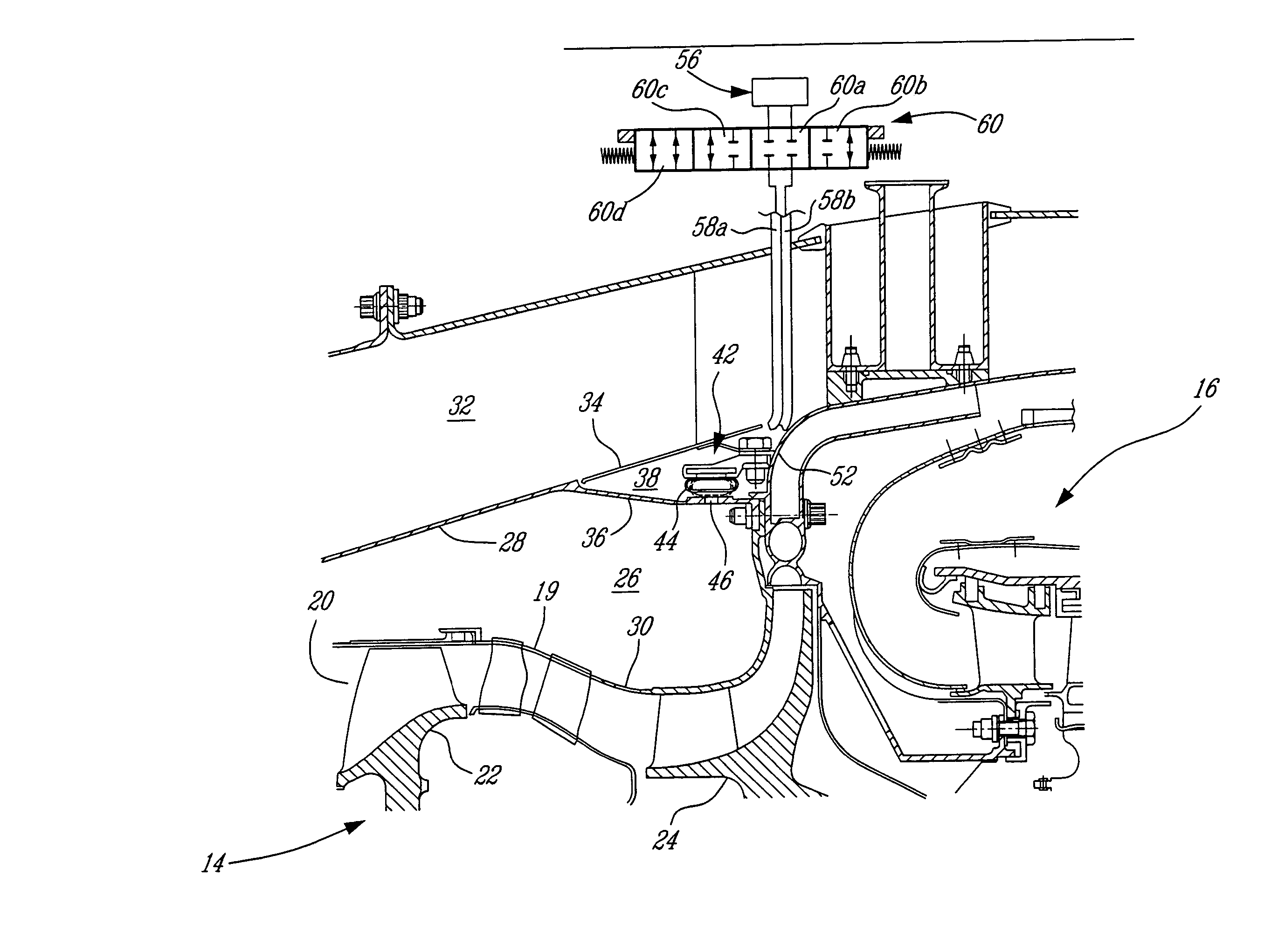
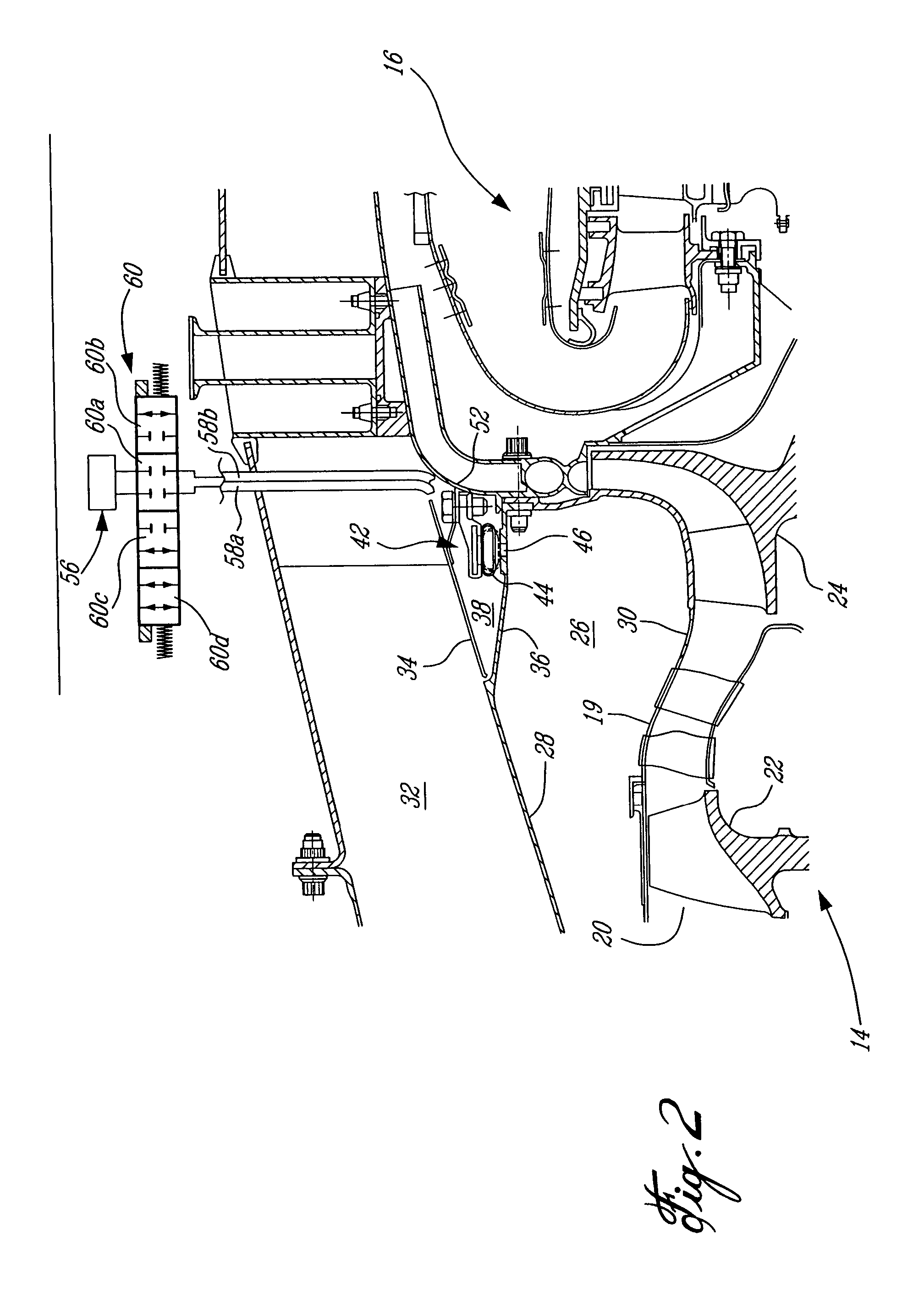
[0018] As shown in FIG. 2, the compressor 14 comprises among others a shroud 19 defining an axially extending compressor flow path 20 in which are typically placed a low pressure rotor 22 followed by a high pressure rotor 24 for compressing the air flowing longitudinally through the compressor flow path 20. An annular plenum 26, radially bounded by the shroud 19 and a partition 28, circumscribes the compressor flow path 20. The annular plenum 26 is connected in fluid flow communication with the compressor flow path 20 by means of a series of circumferentially distributed bleed ports 30 defin...


PUM


Abstract

A compressor bleed valve system for bleeding air from a gas turbine engine compressor comprises a bladder inflatable between at least a collapsed position and an expanded position for selectively opening and closing a compressor airbleed passage.

Description

BACKGROUND OF THE INVENTION [0001] 1. Field of the Invention [0002] The present invention relates to gas turbine engines and, more particularly, to a system for bleeding air from a gas turbine engine compressor. [0003] 2. Description of the Prior Art [0004] Gas turbine engines are generally provided with a compressor bleed valve system adapted under some operating conditions to bleed off compressor air before a surge condition is to happen. [0005] Such compressor bleed valve systems typically comprise a plurality of valves circumferentially distributed about the compressor housing and linked to an actuator for synchronous operation. This leads to heavy and complex arrangements. Furthermore, each valve typically comprises a relatively large number of moving parts that are subject to premature wear due friction forces. SUMMARY OF THE INVENTION [0006] It is therefore an aim of the present invention to provide a simplified compressor bleed valve system. [0007] It is also an aim of the p...

Claims


Application Information

Patent Timeline
IPC IPC(8): F01D17/10F01D25/12F02C9/18F03D1/00F04D27/02
CPCF01D17/105F04D27/0215F02C9/18F04D27/023
Inventor ELEFTHERIOU, ANDREAS
Owner PRATT & WHITNEY CANADA CORP
Why Eureka
Try Eureka