Magnetic tension control weight training machine

Active Publication Date: 2005-01-13
YEH YONG SONG
View PDF4 Cites 22 Cited by
  • Summary
  • Abstract
  • Description
  • Claims
  • Application Information

AI Technical Summary

Benefits of technology

[0003] The main objective for the present invention is to provide a magnetic tension control weight training machine with a precise control over the resistance force through a large r

Problems solved by technology

Such a spring, however, loses its flexibility after a while, making

Method used


Image

  • Magnetic tension control weight training machine
  • Magnetic tension control weight training machine
  • Magnetic tension control weight training machine

Examples


Example

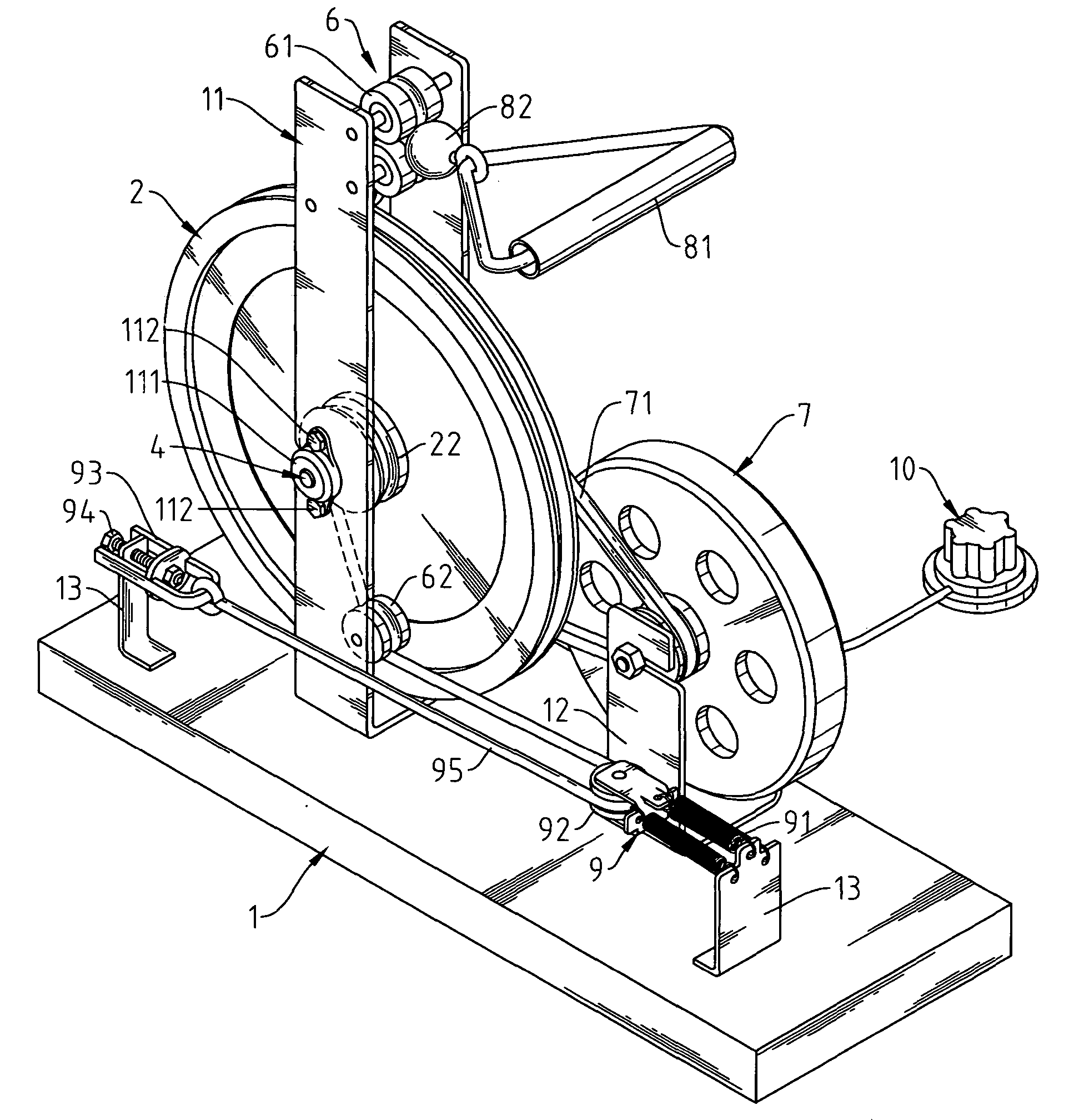
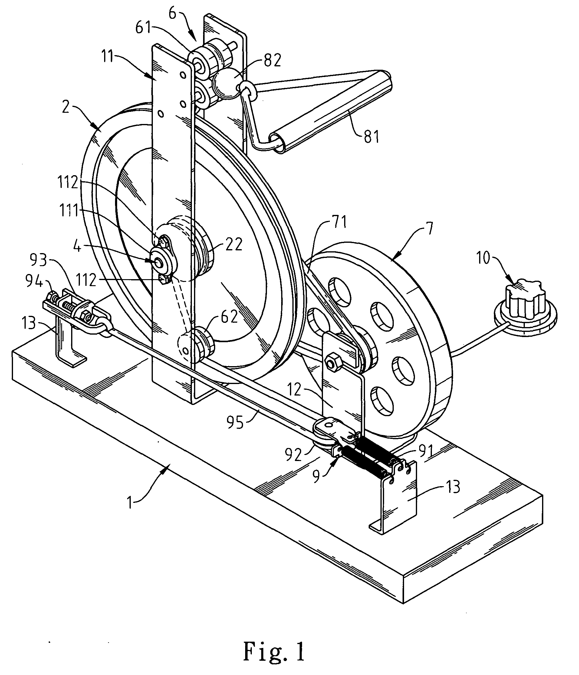
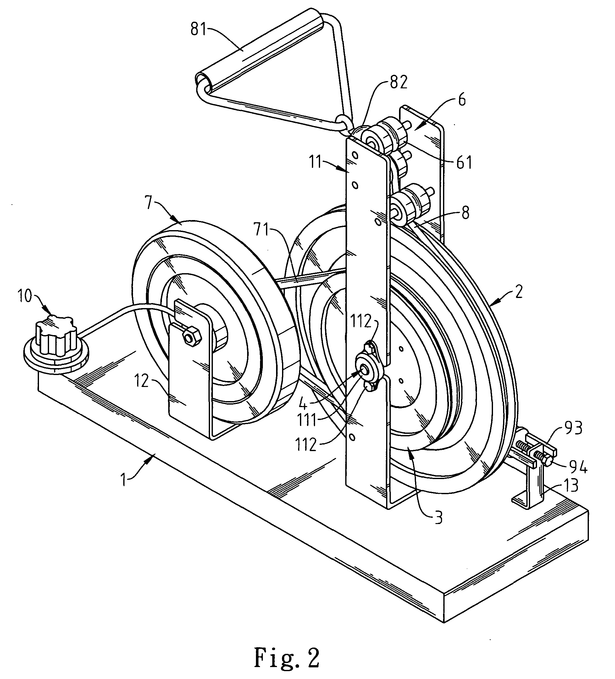
[0011] Please refer to FIG. 1 to FIG. 3. The magnetic tension control weight training machine mainly contains a base 1, a large revolver wheel 2, a belt disc 3, a shaft set 4, a bearing assembly 5, a pulley assembly 6, a magnetic resistance flywheel 7, a pulling rope 8 and a reposition device 9. Two braces 11, 12 are fixed upon the base 1, where the brace 11, 12 allows for the placement of the large revolver wheel 2 and the magnetic resistance flywheel 7 and other components, specifically, the brace 11 is for the placement of the large revolver wheel 2, the belt disc 3, the shaft set 4, the bearing assembly 5 and the pulley assembly 6. The wheel spacer 21 of the large revolver wheel 2 contains the bearing assembly 5 wherein there is one way bearing 51 and two other bearings 52. The other two bearings 52 could be metallic bushings, the mechanism of one way bearing can prevents the large revolver wheel 2 from being unintentionally rotated reversibly after in motion of revolving.

[0012...


PUM


Abstract

The present invention relates to a magnetic tension control weight training machine containing a base, large revolver wheel, belt disc, shaft set, bearing assembly, pulley assembly, magnetic resistance flywheel, pulling rope and a reposition device. A wheel spacer is welded to the center of the large revolver wheel within which there is a bearing assembly, on one side fixed with a small revolver wheel for reposition. The shaft set fits through the bearing assembly, one end welded with a shaft disc to fasten the belt disc that is connected with the magnetic resistance flywheel and the large revolver wheel by means of the belt. The size of the small revolver wheel and the active pulley makes the extension length of the flexible components quite short. The reposition device adjusts the reposition course through the active pulley and the adjustment blot, allowing for the control of the force.

Description

FIELD OF THE INVENTION [0001] The present invention relates to a magnetic tension control weight training machine that provides multiple body-building exercises such as rowing training and physical strength training. BACKGROUND OF THE INVENTION [0002] Traditional tension control weight training machine only provides a single function, either hand / feet training or extension training. In order to make the weight training machine as small as possible for the purpose of convenience, the weight training machine is usually made quite simple in its mechanical structures with load-bearing structure and the flexible spiral spring. Such a spring, however, loses its flexibility after a while, making it unable to reposition the pulling rope back to the original place. When the force enact on the machine terminates, a strong back pulling force occurs that applies on the user when the rope is on its way back to the start point. SUMMARY OF THE INVENTION [0003] The main objective for the present in...

Claims


Application Information

Patent Timeline
IPC IPC(8): A63B21/00A63B21/005A63B21/22A63B22/00A63B69/06
CPCA63B21/005A63B21/153A63B2022/0079A63B22/0076A63B21/225
Inventor YEH, YONG-SONG
Owner YEH YONG SONG
Why Eureka
Try Eureka