

Claw pole motor stator
a stator and claw technology, applied in the field of claw pole motor stators, can solve the problems of disadvantageous increase of axial dimensions of stators, large disadvantageous thickness of stator units, and difficulty for conventional motors to meet the objective of reducing the axial thickness of claw pole motors.
- Summary
- Abstract
- Description
- Claims
- Application Information
AI Technical Summary
Benefits of technology
Problems solved by technology
Method used
Image

Examples
second embodiment
[0082] the present invention is now explained with reference to FIGS. 8A and 8B.
first embodiment
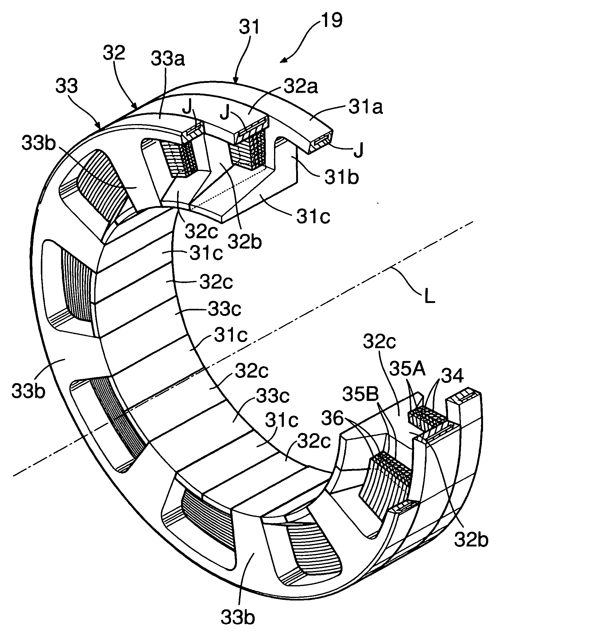
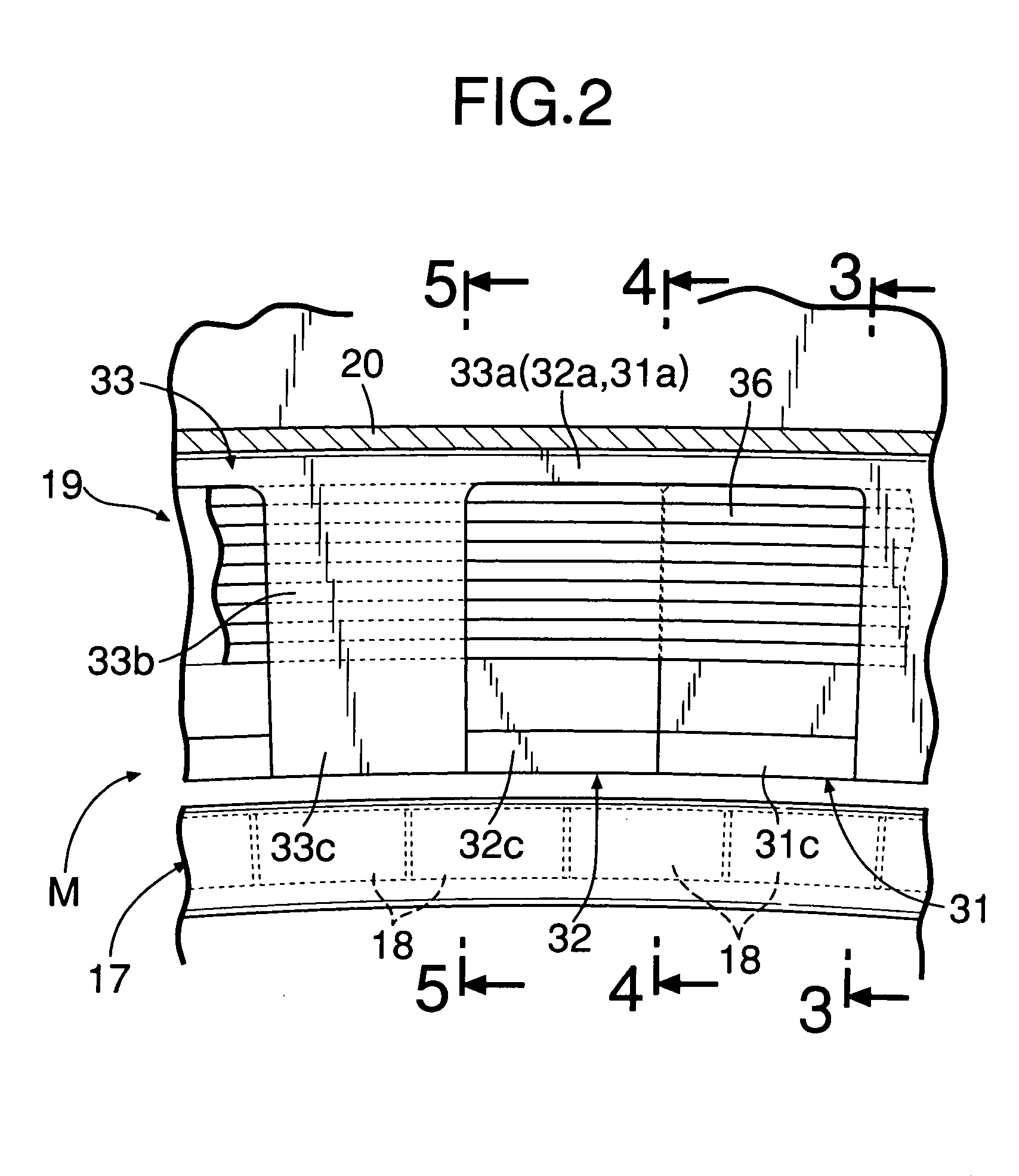
[0083] The U-phase, V-phase, and W-phase teeth 31b, 32b, and 33b, respectively, of the stator 19 of the first embodiment are arranged at different phases in the peripheral direction. Also, the poles 31c, 32c, and 33c extending in the axial L direction from the radially inner ends of the teeth 31b, 32b, and 33b have the same length as the thickness in the axial L direction of the stator 19. The width of the permanent magnets 18 of the rotor 17 is the same as the width of the poles 31c, 32c, and 33c. Additionally, the permanent magnets 18 are shared between the poles 31c, 32c, and 33c of the respective phases.
[0084] In contrast, U-phase, V-phase, and W-phase teeth 31b, 32b, and 33b of a stator 19 of the second embodiment are arranged in phase with each other. Also, poles 31c, 32c, and 33c extending radially inward from the teeth 31b, 32b, and 33b are also arranged in phase with each other. However, the permanent magnets 18 disposed on the outer periphery of a rotor 17 are arranged in ...
PUM
 Abstract
Description
Claims
Application Information