Multi-coil coupling system for hearing aid applications

a coupling system and hearing aid technology, applied in the direction of electrical equipment, deaf-aid sets, etc., can solve the problems of high background noise, hearing impaired individuals may require a hearing solution, and high level of background noise, so as to avoid buildup of magnetic field strength and minimize the thickness of the inductor pair

Inactive Publication Date: 2007-04-17
III HLDG 7
View PDF16 Cites 74 Cited by
  • Summary
  • Abstract
  • Description
  • Claims
  • Application Information

AI Technical Summary

Benefits of technology

[0044]In an embodiment according to the present invention, the at least one inductor may comprise at least two transmit inductors positioned to magnetically couple with a vertically-oriented telecoil located within the hearing aid. The at least two transmit inductors may comprise coils. The coils may comprise windings. The windings may be divided into at least two windings spaced a distance apart by winding gaps on each of the at least two transmit inductors. The winding gaps may permit one transmit inductor to overlap a center of another transmit inductor to minimize thickness of an inductor pair while allowing the one transmit inductor to be positioned to couple with the at least one telecoil in the hearing aid.
[0045]In an embodiment according to the present invention, the hearing improvement device may produce a flat frequency response at an output of a receiving telecoil. Frequency-dependent drive voltage response may compensate for a combined frequency response. A transmit inductor drive voltage may produce a flat receiving telecoil frequency response. Overall magnetic coupling response may be uniform over a speech frequency range.
[0046]In an embodiment according to the present invention, the at least one inductor may comprise an inductor pair. Each inductor of the inductor pair may comprise a coil having at least two windings spaced a distance apart by a winding gap. The winding gap of each inductor of the inductor pair may permit one inductor of the inductor pair to overlap another inductor of the inductor pair at the winding gap of each inductor. The overlapped inductors may avoid buildup of magnetic field strength near a center of each inductor that would occur with a continuous winding. The overlapped inductors may provide a magnetic field adapted to couple to a variety of hearing aids types comprising a range of receiving telecoil positions.

Problems solved by technology

In many situations, however, hearing impaired individuals may require a hearing solution beyond that which can be provided by such a hearing aid using an internal microphone alone.
For example, hearing impaired individuals often have great difficulty carrying on normal conversations in noisy environments, such as parties, meetings, sporting events, etc., involving a high level of background noise.
In addition, hearing impaired individuals also often have difficulty listening to audio sources located at a distance from the individual or to several audio sources located at various distances from the individual and at various positions relative to the individual.
The characteristics and location of a hearing aid internal microphone often results in excessive pickup of ambient acoustical noise.
A common problem with prior art tele-couplers of the neck loop and silhouette styles has been the difficulty of bathing the telecoil in a magnetic field that is both of sufficient strength and sufficient uniformity in relation to typical relative tele-coupler / telecoil positionings to ensure a predictable, consistent audio coupling at a volume level adequate for comfortable use and that can consistently overcome environmental magnetic noise interference.
Additionally, silhouette style tele-couplers, which are generally designed with BTE aids in mind, have not successfully achieved sufficient field strength at the greater distances needed to reach the ITE telecoils, or provided an appropriate field orientation for optimum coupling.
Further, the net frequency response obtained with prior art tele-coupler / telecoil systems has been uncontrolled, unpredictable, and not generally uniform.
The combination of the non-uniform frequency characteristics of the field produced by the typical transmitting inductor and the non-uniform frequency response of the typical receiving telecoil results in unsatisfactory overall frequency response for the user.

Method used


Image

  • Multi-coil coupling system for hearing aid applications
  • Multi-coil coupling system for hearing aid applications
  • Multi-coil coupling system for hearing aid applications

Examples


Embodiment Construction

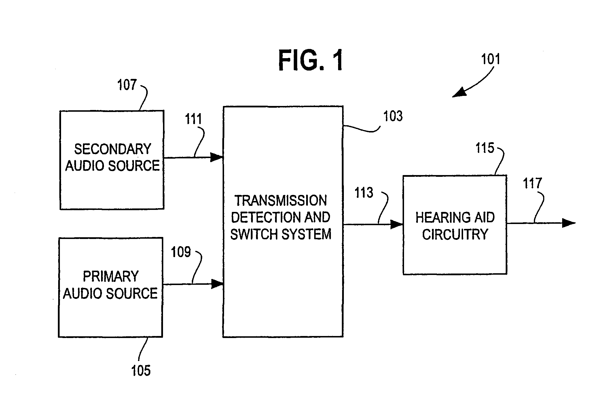
[0101]FIG. 1 is a block diagram of an overall hearing improvement system 101 according to the present invention. A transmission detection and switch system 103 may receive signals from both a primary audio source 105 and a secondary audio source 107. The primary audio source 105 may be, for example, a directional or omnidirectional microphone located in a hearing aid. The secondary audio source 107 may be, for example, a directional microphone / transmitter mounted on eyeglasses (or otherwise supported by a hearing aid user), a television or stereo transmitter, a telephone, or a microphone / transmitter combination under the control of a talking user. In an embodiment according to the present invention, secondary audio source 107 may utilize a wireless transmission scheme for transmission of signals to the transmission detection and switch system 103. In another embodiment according to the present invention, the secondary audio source 107 may be wired to the transmission detection and s...


PUM


Abstract

Disclosed herein is a hearing improvement device using a multi-coil coupling system and methods for operating such a device. In an embodiment according to the present invention an array microphone may be used to provide highly directional reception. The received audio signal may be filtered, amplified, and converted into a magnetic field for coupling to a telecoil in a conventional hearing aid. Multiple transmit inductors may be used to effectively couple to both in-the-ear and behind-the-ear type hearing aids, and an additional embodiment is disclosed which may be used with an earphone, for users not requiring a hearing aid.

Description

CROSS-REFERENCE TO RELATED APPLICATIONS / INCORPORATION BY REFERENCE[0001]The present application claims the benefit of priority of U.S. Provisional Patent Application having Ser. No. 60 / 459,865, filed on Apr. 1, 2003, and hereby incorporates herein by reference the complete subject matter thereof, in its entirety.[0002]The present application also hereby incorporates herein by reference the complete subject matter of U.S. Provisional Patent Applications having Ser. No. 60 / 174,958, filed Jan. 7, 2000, Ser. No. 60 / 225,840, filed on Aug. 16, 2000, in their respective entireties.[0003]The present application is also a continuation in part of U.S. Non-Provisional Application having Ser. No. 10 / 356,290 entitled “Multi-Coil Coupling System for Hearing Aid Applications” filed on Jan. 31, 2003, which is hereby incorporated herein by reference, in its entirety.[0004]The present application is also a continuation in part of U.S. Non-Provisional Application having Ser. No. 09 / 752,806 entitled “T...

Claims


Application Information

Patent Timeline
Patent Type & Authority Patents(United States)
IPC IPC(8): H04R25/00
CPCH04R25/558
Inventor JULSTROM, STEVEN D.KILLION, MEAD
Owner III HLDG 7
Why Eureka
Try Eureka