Drive arrangement, especially for a lifting mechanism and/or a traveling drive

Active Publication Date: 2005-01-20
KONECRANES GLOBAL
View PDF10 Cites 4 Cited by
  • Summary
  • Abstract
  • Description
  • Claims
  • Application Information

AI Technical Summary

Benefits of technology

[0014] This enables a switching without jerks between various speeds. When the motor is accelerating from standstill, this is accomplished with a low starting current of the motor. For this, the high-pole winding is first switched and upon reaching the desired rated number of revolutions, there is a switch to the low-pole winding for high speeds. On the contrary, to slow down the motor from a fast speed, a slowdown without jerks is achieved by switching the high-pole winding when the synchronous speed is achieved. Thus, one can accomplish a change in direction by slowing down to standstill and accelerating or restarting in the opposite direction.
[0015] In addition, it is possible to control the optimal switching time, even with changeable loads, and for both directions of turning. The acceleration or its time to achieve the desired rated speed depends on the load and the direction of turning. Thus, with heavy loads being lifted, longer acceleration times occur, and with heavy loads being lowered, shorter acceleration times. These effects can be avoided or compensated by synchronization.
[0016] In one embodiment, a brake, especially an electromechanical brake, can be provided, whose actuation during the braking process will depend on the speed of the rotary-current motor. The switching event during the braking can also be synchronized with the speed of the rotary-current motor. The synchronization is advantageously embodied by the rotary-current motor and its actuation by means of the control logic. Thus, it is possible for a braking process in generator mode or a braking process with reverse current to be switched off at the proper speed. In addition, a mechanical brake can be provided

Problems solved by technology

Interruption of the current during inductive loads, which are produced here by the motor windings, results in sparking at the contacts.
The space requirement and costs of the contactors increase out of proportion to the power being switched.
Instead of cont

Method used


Image

  • Drive arrangement, especially for a lifting mechanism and/or a traveling drive
  • Drive arrangement, especially for a lifting mechanism and/or a traveling drive
  • Drive arrangement, especially for a lifting mechanism and/or a traveling drive

Examples


Embodiment Construction

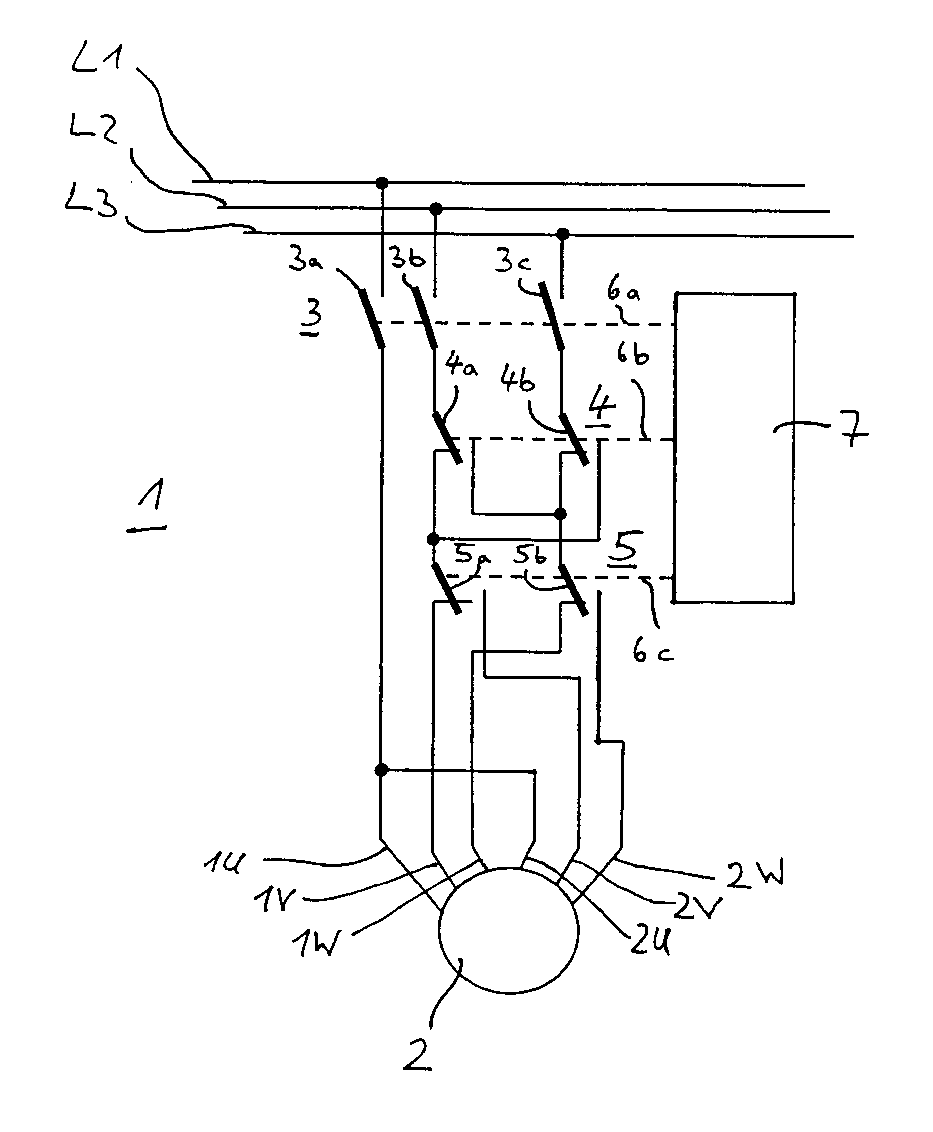
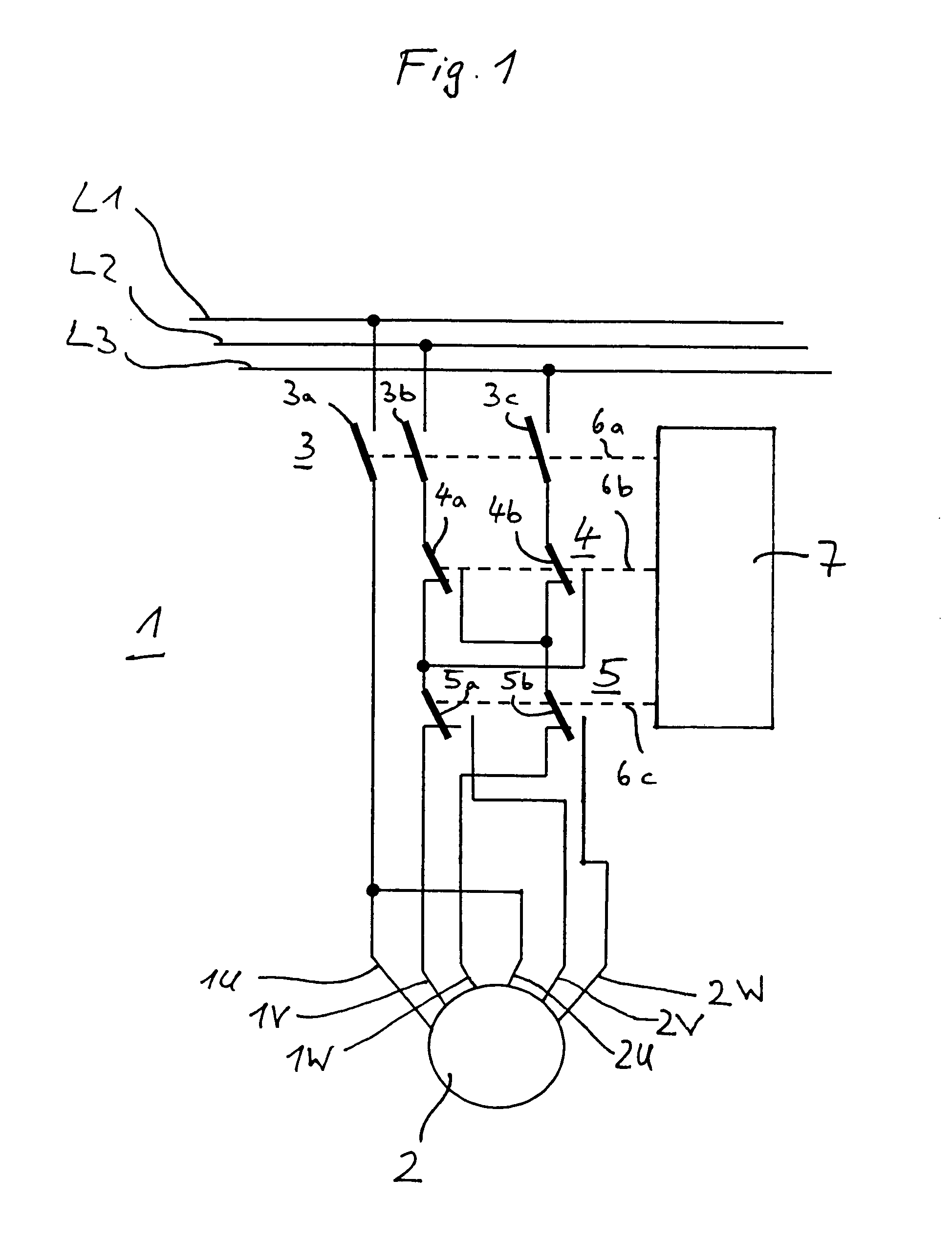
[0023] The invention shall now be explained more closely by means of a first sample embodiment represented in FIG. 1. FIG. 1 shows a driving circuit 1 for a pole-reversible rotary-current motor 2, in particular, a rotary-current induction motor. The rotary-current motor 2 has two three-phase windings with different numbers of pole pairs, designated by the letters 1U, 1V, 1W, 2U, 2V and 2W.

[0024] The driving circuit 1, and thus also the rotary-current motor 2, is provided with energy via a rotary-current supply, of which the strands L1, L2 and L3 are shown. The drive circuit 1 consists here basically—looking from the strands L1, L2, L3 in the direction of the rotary-current motor 2—of a load switch element 3, which is connected to a reversing switch element 4 and a pole switching element 5.

[0025] The load switching element 3 is configured as a traditional power contactor with three power switch contacts 3a, 3b, 3c, which are associated accordingly at the input side with the three s...


PUM


Abstract

The invention concerns a drive arrangement of a lifting gear and/or a traveling gear, with a pole-reversible rotary-current motor with windings for at least two different actuating speeds, with a pole switching element connecting the rotary-current motor to a voltage supply for changing between the actuating speeds of the rotary-current motor. In order to create a drive arrangement of a lifting gear and/or a traveling gear with a rotary-current motor, whose switching behavior is optimized in relation to the actuation of the rotary-current motor, it is proposed that a power switching element (3) be hooked up in front of the pole switching element (5), and it can be separated from the voltage supply via the power switching element (3) for the pole switching process of the rotary-current motor (2).

Description

BACKGROUND OF THE INVENTION [0001] The invention concerns a driving arrangement of a lifting gear and / or a traveling drive, particularly one having a pole-reversible rotary current motor with windings for at least two different drive speeds and with a pole switching element connecting the rotary current motor to a voltage supply in order to switch between the driving speeds of the motor. [0002] In the state of the art, it is generally known how to employ electrical pole-reversible rotary-current induction motors for the horizontal or vertical movement of loads, for example, in traveling or lifting gears, whose direction of movement is reversible, in that two of the rotary current phases are exchanged with a reversing circuit. In addition, these rotary-current induction motors can have several windings, which have different numbers of pole pairs. Thus, the possibility exists of changing the rotary speed of the motor by a so-called pole reversal between the motor windings with the dif...

Claims


Application Information

Patent Timeline
IPC IPC(8): B66C13/26B66C13/30H02P1/38H02P23/00H02P25/20
CPCB66C13/26H02P23/0072H02P1/38B66C13/30H02P23/24
Inventor FREITAG, HOLGERMUNZEBROCK, ANTONHASENACK, BURKHARDPERSICO, GIULIANOAPPEL, ERIK
Owner KONECRANES GLOBAL
Why Eureka
Try Eureka