Method for determining a switching time of an electrical switching device

A technology of electrical switches and switching times, applied in the direction of electrical switches, electrical components, circuits, etc., can solve the problems of expensive, undeterminable switching times, etc., and achieve the effect of cost reduction

Inactive Publication Date: 2014-08-13
SIEMENS AG
View PDF4 Cites 0 Cited by
  • Summary
  • Abstract
  • Description
  • Claims
  • Application Information

AI Technical Summary

Problems solved by technology

[0004] The method described in DE 10 2005 005 228 A1 is expensive because in it multiple successive zero crossings of the drive voltage and the resulting voltage have to be considered in a correlation and weighted using different criteria
Another method of pattern recognition does not always lead to the desired result, since the envelope of the voltage established across the breaker gap has a frequency which depends on the degree of compensation of the overhead line and thus on the resonant frequency of the resonant circuit, making it possible to determine Such a zero crossing of the envelope in the time window of is not within the time window when the degree of compensation is changed, and therefore the best possible switching moment cannot be determined

Method used


Image

  • Method for determining a switching time of an electrical switching device
  • Method for determining a switching time of an electrical switching device
  • Method for determining a switching time of an electrical switching device

Examples


Embodiment Construction

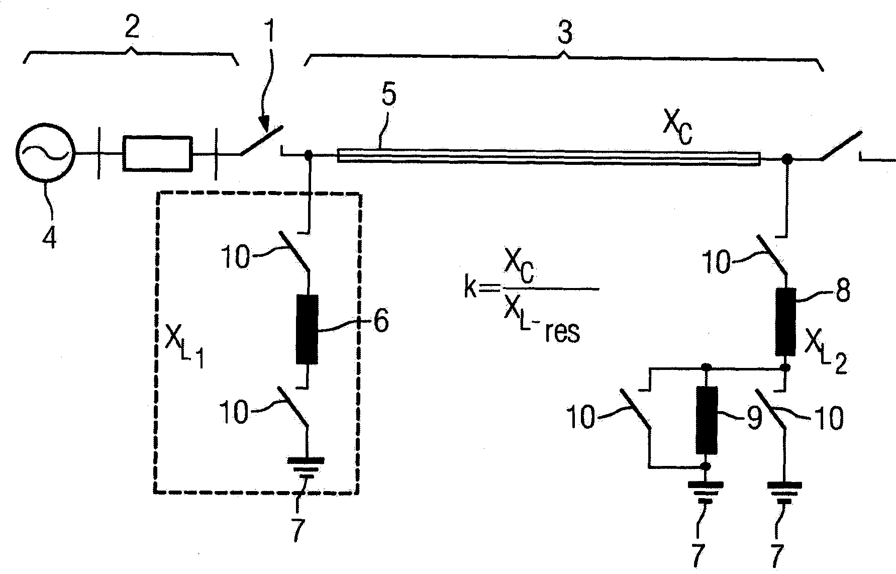
[0020] figure 1 The schematic structure of a line section within a power transmission network is shown. The electrical switch has a breaker gap 1 which is formed, for example, by two contact elements which are movable relative to one another. The first line part 2 and the second line part 3 can be connected to each other or separated from each other through the circuit breaker gap 1 . The first line part 2 has a generator 4 which supplies a driving voltage, for example a 50 Hz alternating voltage of a polyphase alternating current system. The second line part 3 has an overhead wire 5 which is connectable at its first end to ground potential 7 via a first choke coil 6 and at its second end to ground potential via a second choke coil 8 7 connections. Furthermore, it can additionally also be proposed to connect a further choke coil 9 to the second choke coil 8 . Via different switching devices 10 , the inductor coils 6 , 8 , 9 can be connected to ground potential in different...


PUM


Abstract

To devise a method for determining the switching moment of an electrical switching device with a first line part (2) arranged on which a driving voltage (4) is applied and a second line part (2) forming a resonant circuit after the switch-off process of the switching device Circuit breaker gaps (1) between line sections (3), with which the best possible switching moments of electrical switching devices can be determined to minimize transient overvoltages, it is recommended to: determine the establishment during the sampling period (t1) The time history of the voltage across the breaker gap (1), from which the resonance frequency of the resonant circuit is determined and from which the time window (Δt) is determined again, and after a defined time period (t2) has passed after the switch-off process The switching instant is asserted within this time window (Δt) from the zero-crossing determination of the envelope corresponding to the resonant frequency of the future history of the time-history calculation; ), from the determined time history the future time history of the voltage across the breaker gap and the resonant frequency of the resonant circuit, and from this in turn the time window (Δt) is determined and defined after the switch-off process The zero-crossing determination of the voltage across the breaker gap weighted by the drive voltage and the resonant circuit voltage after a time period (t2) of , is used to determine the switching instant within the determined time window (Δt).

Description

technical field [0001] The invention relates to a method for determining the switching moment of an electrical switching device with a circuit breaker gap arranged between a first line section to which an operating voltage is applied and a second part forming a resonant circuit after the switch-off process of the switching device. between the two line sections. Background technique [0002] Such a method is known, for example, from DE 10 2005 005 228 A1. Said document discloses a method for determining the switching times of an electrical switching device in the form of a gas-insulated switchgear, which can connect or disconnect a first line section with a generator for use in A second line part in the form of an overhead line supplies the first line part with a drive voltage. Such an overhead line forms a resonant circuit in a known manner after the opening of the electrical switching device and the separation of the first line part carrying the generator and the drive vo...

Claims


Application Information

Patent Timeline
Patent Type & Authority Patents(China)
IPC IPC(8): H01H9/56
CPCH01H9/56H01H2009/566Y10T307/76
Inventor 汉斯-乔格·里克特克里斯琴·沃尔纳
Owner SIEMENS AG
Why Eureka
Try Eureka