Data transfer apparatus and its control method

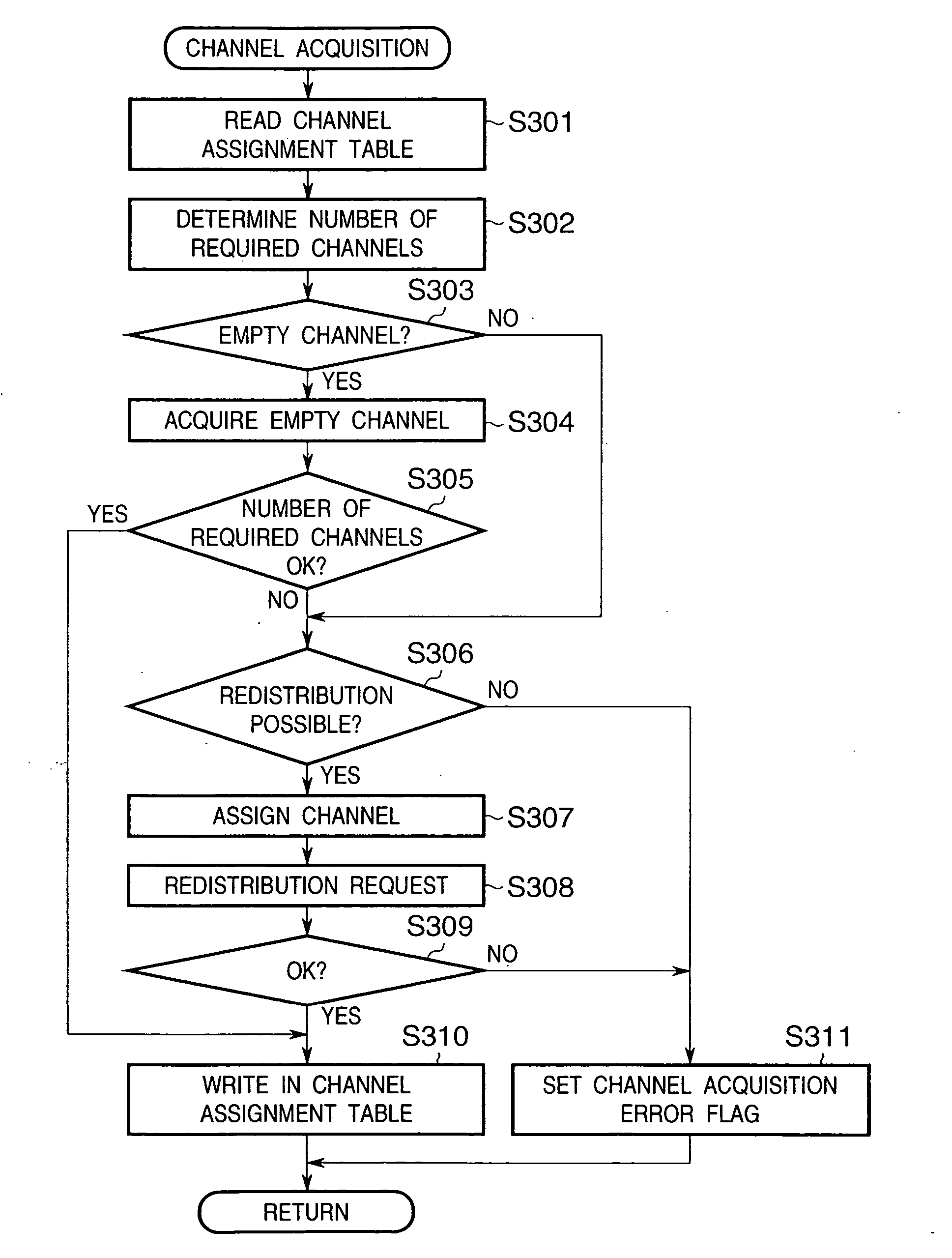
a data transfer and control method technology, applied in the field of data transfer apparatuses, can solve problems such as failure to ensure the required number of channels, and achieve the effect of preventing data transfer from failing

Inactive Publication Date: 2005-01-20
CANON KK
View PDF17 Cites 9 Cited by
  • Summary
  • Abstract
  • Description
  • Claims
  • Application Information

AI Technical Summary

Benefits of technology

[0005] The present invention has been made in consideration of the aforementioned prior art, and has as its object to provide an image processing system including a data transfer apparatus, which, if there is a device which cannot assure a required number of channels, adjusts the total number of channels required including those already assured by some other device, and can prevent data transfer from failing due to an insufficient number of channels.
[0008] Alternatively, to attain the adjustment, the number of channels required by the device that issued the new channel request is decreased.
[0015] More preferably, the adjustment means decreases the number of channels to limit the sum to a value not more than the predetermined number by reducing a data transfer rate of the device to which channels have already been assigned, when the sum of the number of channels required for new data transfer and the number of already assigned channels exceeds the predetermined number.
[0016] More preferably, the adjustment means decreases the number of channels to limit the sum to a value not more than the predetermined number by reducing a data transfer rate of new data transfer, when the sum of the number of channels required for new data transfer and the number of already assigned channels exceeds the predetermined number.

Problems solved by technology

In high-speed serial communications such as IEEE1394, since the number of channels capable of data transfer in each prescribed cycle time interval is limited, if a given device has assured channels in such conventional image processing system, another device often fails to assure a required number of channels.

Method used


Image

  • Data transfer apparatus and its control method
  • Data transfer apparatus and its control method
  • Data transfer apparatus and its control method

Examples


first embodiment

[0049] [First Embodiment]

[0050] The first embodiment of the present invention will be described below with reference to the accompanying drawings.

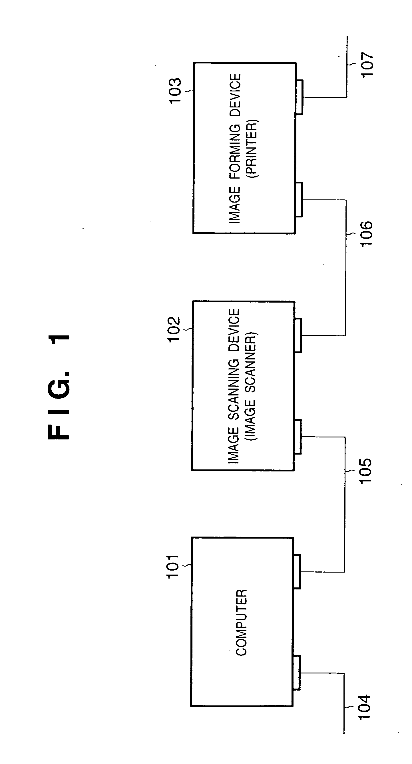
[0051]FIG. 1 is a diagram showing the arrangement of an image processing system according to an embodiment of the present invention. Referring to FIG. 1, a computer 101 is the one used by an ordinary user, and is connected to an image scanning device 102 such as an image scanner or the like, which converts an image signal scanned by, e.g., a CCD into digital data, and outputs the digital data, via a high-speed serial communication I / F 105. Furthermore, the image scanning device 102 is connected to an image forming device 103, such as an electrophotographic printer or the like, via a high-speed serial communication I / F 104. The image forming device 103 is connected to another device (not shown) via a high-speed serial communication I / F 107 as needed.

[0052] With this arrangement, the computer 101 is also connected to the image forming devi...

second embodiment

[0249] [Second Embodiment]

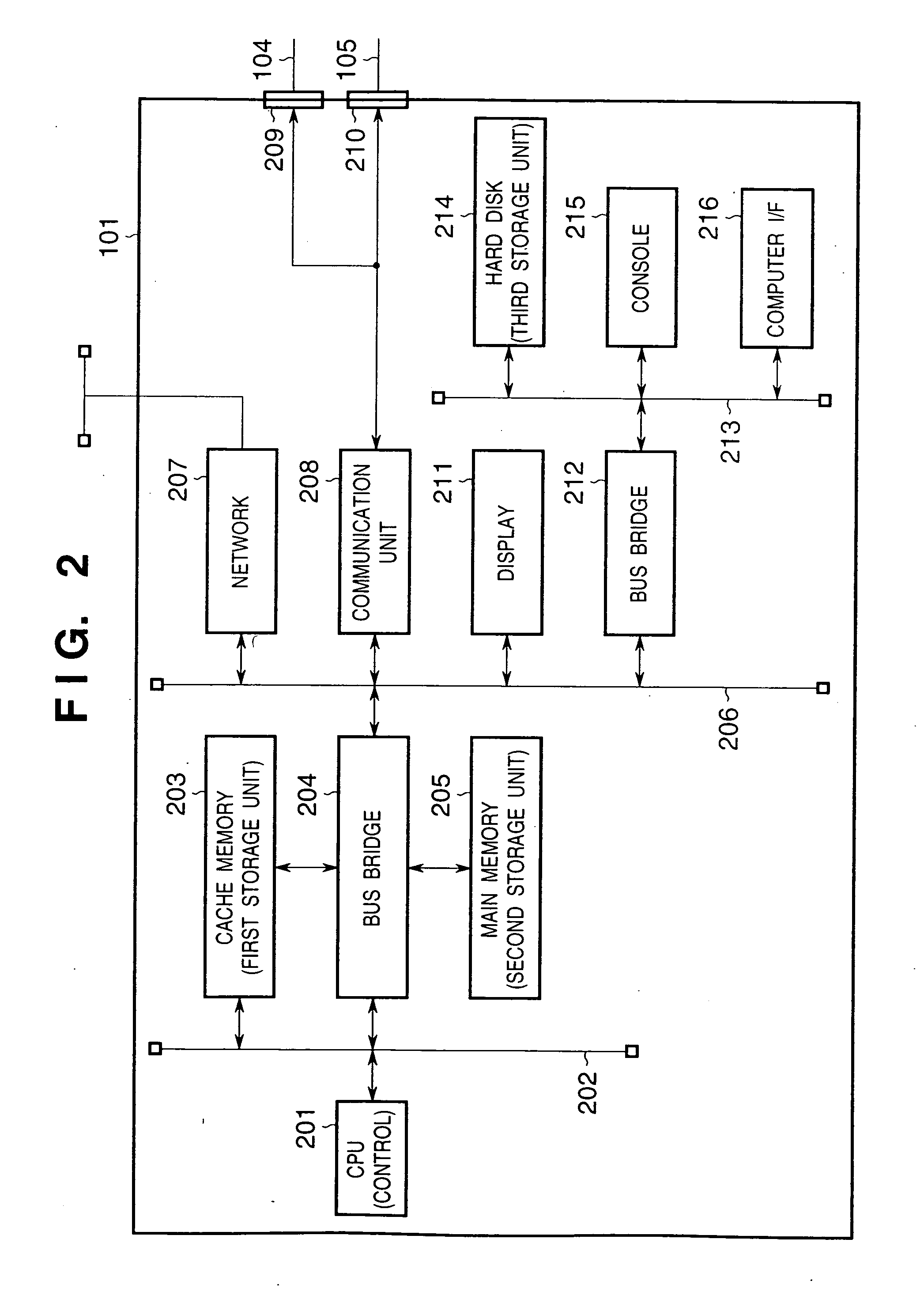
[0250] An image processing system in the second embodiment has the same arrangement as that in the first embodiment shown in FIG. 1. The computer 101 has the arrangement shown in FIG. 2, the image scanning device 102 has the arrangement shown in FIGS. 3 and 17, and the image forming device 103 has the arrangement shown in FIGS. 4 and 18. The image processing system of this embodiment is different from that in the first embodiment in a procedure for acquiring channels.

[0251] The print operation in the image processing system of this embodiment will be explained below with reference to FIGS. 19A to 28.

[0252]101>

[0253]FIGS. 19A-19B are flow charts showing the main routine upon executing a print process in the computer 101 of this embodiment. The print operation in the computer 101 will be explained below with reference to FIGS. 19A-19B.

[0254] In step S1901, upon power ON of the computer 101, the control unit 201 initializes flags, registers, control variabl...

third embodiment

[0293] [Third Embodiment]

[0294] The third embodiment of the present invention will be described below.

[0295] In the second embodiment mentioned above, when the number of channels acquired by the image scanning device 102 is insufficient, the operation mode is set to reduce the image scanning speed, thus allowing image scanning while the size of image data to be transferred per unit time is reduced (steps S2212, S2213 in FIG. 22A and S2210 in FIG. 22B). In the third embodiment, when the number of channels acquired by the image scanning device 102 is small, the operation mode is changed and set to obtain single original image data by executing a plurality of scans, e.g., double scans and the like, thereby reducing the size of image data to be transferred per unit time.

[0296] An image processing system in this embodiment is comprised of the computer 101, image scanning device 102, and image forming device 103 shown in FIG. 1 as in the first embodiment described above. Since the detai...


PUM


Abstract

In data transfer in isochronous mode using an IEEE1394 serial bus, the data transfer rate is guaranteed, but data transfer is disabled if the number of channels is insufficient. An already assigned channel is released by lowering the data transfer rate currently using that channel, and the released channel is assigned to new data transfer, thus allowing the new data transfer.

Description

BACKGROUND OF THE INVENTION [0001] The present invention relates to a data transfer apparatus for transmitting / receiving, e.g., image data via communications, and its control method and, more particularly, to a data transfer apparatus of, e.g., an image processing device which outputs a large volume of data onto a communication path and must guarantee a given lower reduce of the data transfer rate like in a case wherein image data is transmitted to and printed by an electrophotographic printer, and its control method. [0002] In recent years, high-speed serial communications such as IEEE1394 and the like begin to be used. [0003] USB, IEEE1394, and the like comprise a mechanism for implementing data transfer with a data transfer rate guaranteed such as isochronous transfer mode. In isochronous transfer mode, since a required number of channels capable of data transfer are assured at prescribed cycle time intervals, a data transfer rate corresponding to the processing performance of a ...

Claims


Application Information

Patent Timeline
Patent Type & Authority Applications(United States)
IPC IPC(8): G06F3/00G06F3/12G06F13/00H04J3/16H04L12/417H04N1/00
CPCH04L12/40058Y02B60/31H04L12/40117H04L12/40123H04L12/4013H04N1/00236H04N1/33353H04N1/33361H04N2201/0015H04N2201/0041H04N2201/0049H04N2201/0081H04N2201/0082H04N2201/33342H04L12/40065Y02D30/50
Inventor YAMAGISHI, YOICHI
Owner CANON KK
Why Eureka
Try Eureka