Method and apparatus for refining target position and size estimates using image and depth data

a target position and depth data technology, applied in image analysis, instruments, computing, etc., can solve the problems of usually not providing accurate information about the target or its movement, and achieve the effect of accurate identifying edges, improving target size estimates, and improving target position information

Active Publication Date: 2005-01-20
FORD MOTOR CO +1
View PDF12 Cites 34 Cited by
  • Summary
  • Abstract
  • Description
  • Claims
  • Application Information

AI Technical Summary

Benefits of technology

[0008] The principles of the present invention provide for a method and apparatus of accurately identifying edges of a nearby target using image intensity and depth information. The principles of the present inven

Problems solved by technology

While vehicle vision systems can identify when a target is in front of a host vehicle, such

Method used


Image

  • Method and apparatus for refining target position and size estimates using image and depth data
  • Method and apparatus for refining target position and size estimates using image and depth data
  • Method and apparatus for refining target position and size estimates using image and depth data

Examples


Embodiment Construction

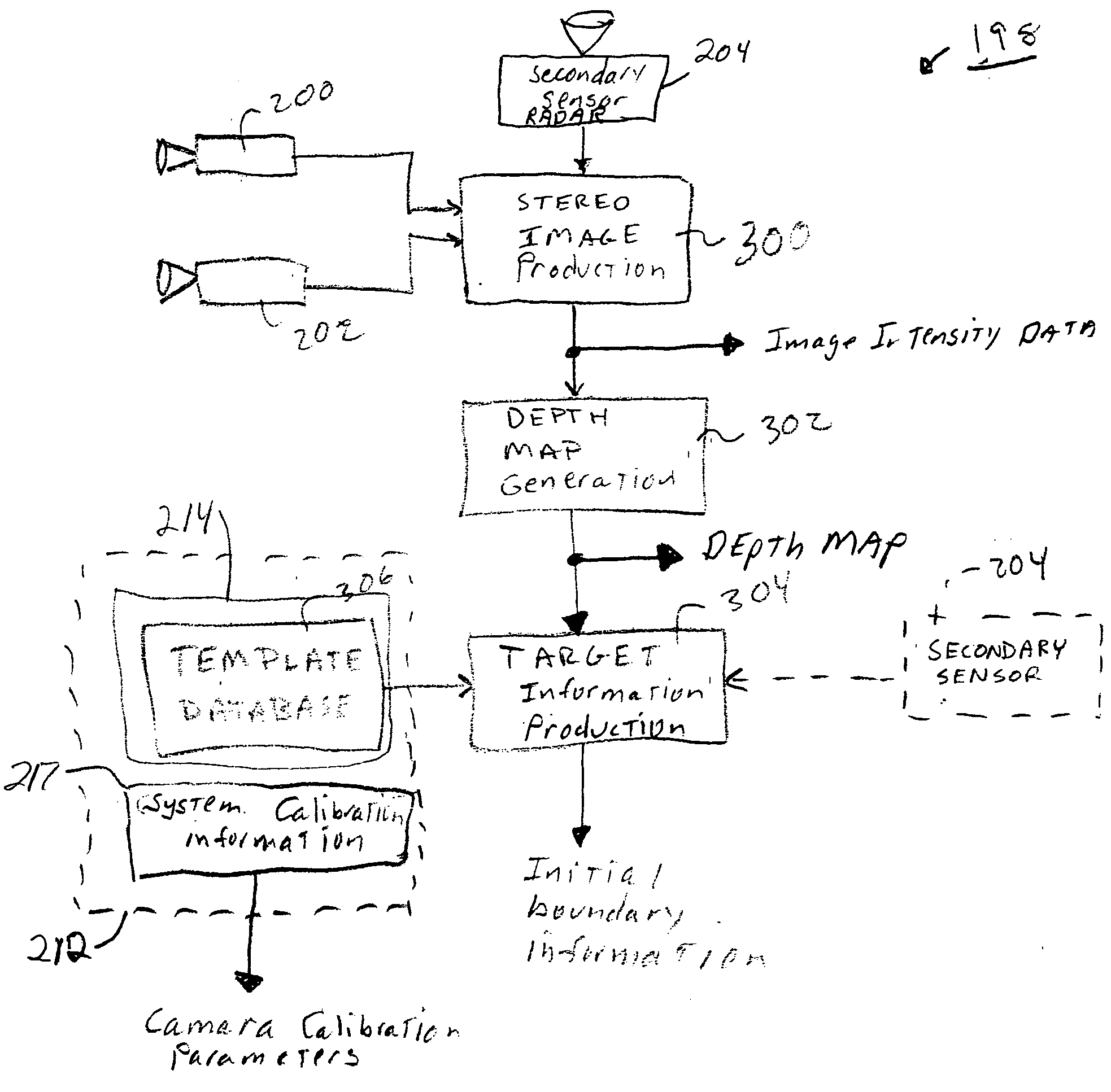
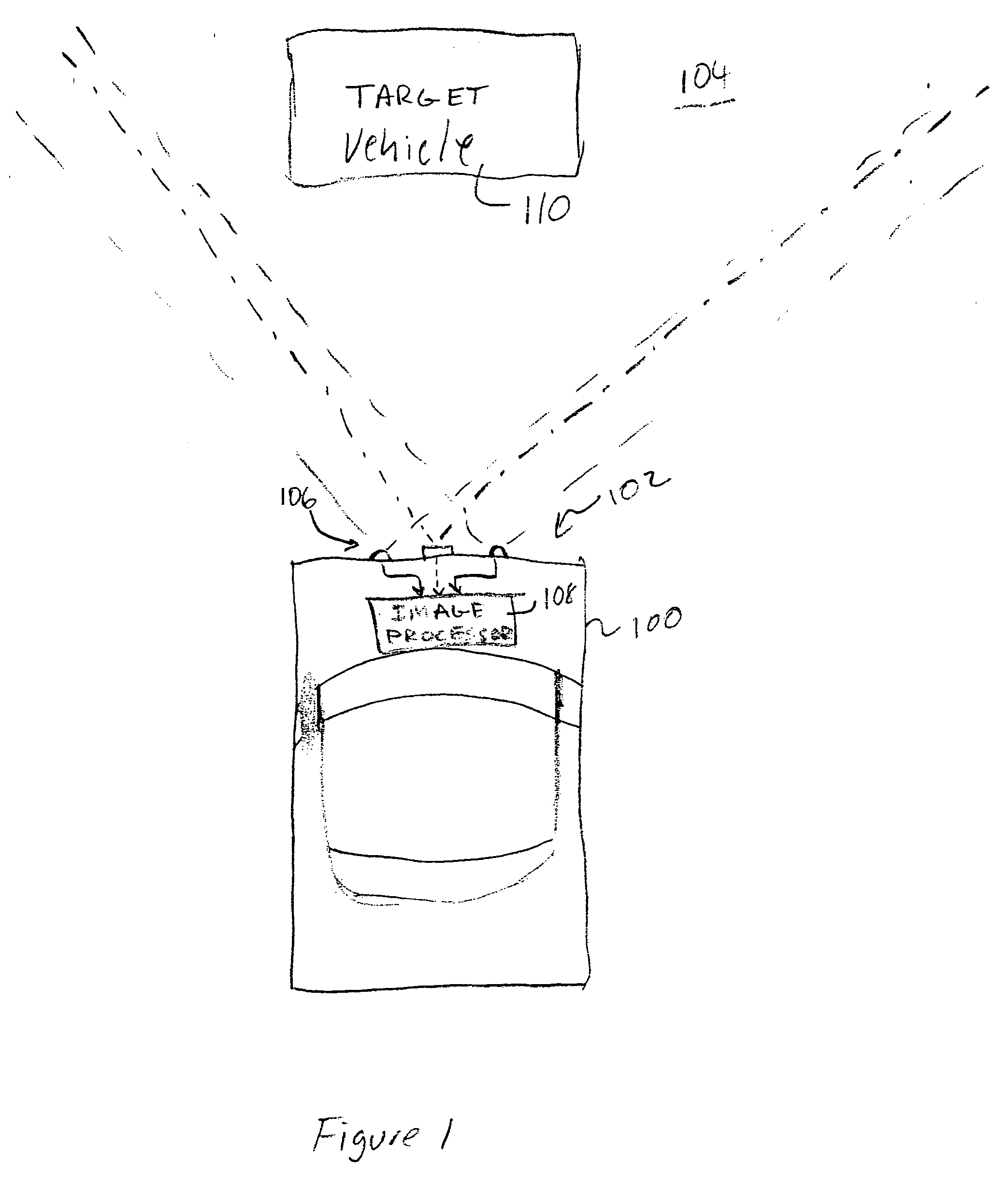
[0023]FIG. 1 depicts a host vehicle 100 having a vision system 102 that images a scene 104 that is in front of the host vehicle 100. Other applications of the vision system 102 may image scenes that are behind or to the side of the host vehicle 100. The vision system 102 includes a sensor array 106 that is coupled to an image processor 108. The sensor array 106 has a field of view that includes a target 110. In practice, the sensor array's field of view may be ±12 meters horizontally (e.g., approximately 3 traffic lanes), ±3 meters vertically, and approximately 40 meters deep.

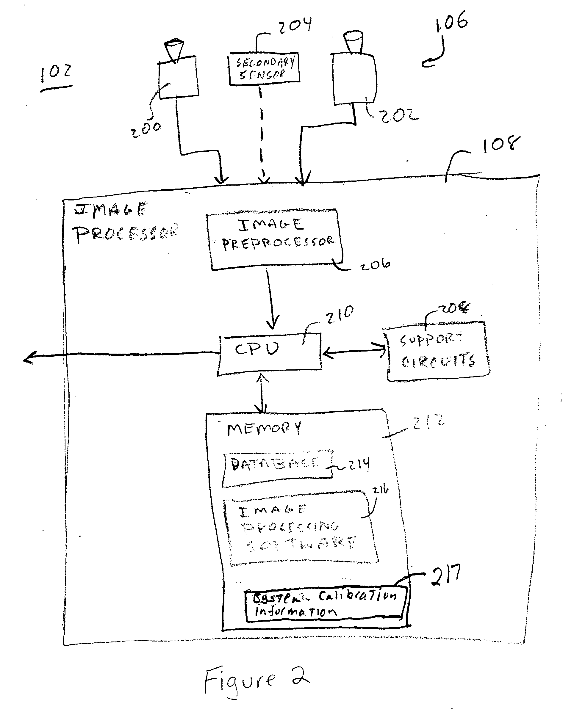
[0024] Referring now to FIG. 2, the sensor array 106 beneficially includes a pair of optical cameras 200 and 202 and a radar-based secondary sensor 204. The cameras 200 and 202 are physically separated at fixed locations to enable stereographic imaging. While the cameras 200 and 202 will typically operate in the visible wavelengths, the cameras may be augmented with infrared sensors, or, in certain application...


PUM


Abstract

A vehicle vision system that uses a depth map, image intensity data, and system calibration parameter to determine a target's dimensions and relative position. Initial target boundary information is projected onto the depth map and onto the image intensity. A visibility analysis determines whether the rear of a target is within the system's field of view. If so, the mapped image boundary is analyzed to determine an upper boundary of the target. Then, vertical image edges of the mapped image boundary are found by searching for a strongest pair of vertical image edges that are located at about the same depth. Then, the bottom of the mapped image boundary is found (or assumed from calibration parameters). Then, the target's position is found by an averaging technique. The height and width of the target are then computed.

Description

CROSS-REFERENCE TO RELATED APPLICATIONS [0001] This application contains subject matter that is related to the subject matter described in U.S. patent application Ser. No. ______, filed Jun. 13, 2003, (Attorney Docket No. SAR / 14885) entitled “Vehicular Vision System”, which is incorporated herein by reference in its entirety.BACKGROUND OF THE INVENTION [0002] 1. Field of the Invention [0003] The present invention relates to vehicle vision systems. More particularly, the present invention relates to improving position and size estimates of nearby vehicles. [0004] 2. Description of the Related Art [0005] Vehicle vision systems include a sensor or sensors that image scenes proximate a vehicle, e.g., in front or behind the vehicle. A vehicle having a vision system will be referred to herein as the host vehicle. A sensor for a vision system may include a radar system, an infrared sensor, an optical system, and the like. In any event, the sensor produces rudimentary image data of the scen...

Claims


Application Information

Patent Timeline
IPC IPC(8): G06T7/00G06V20/00
CPCG06T7/0065G06K9/00624G06T7/55G06V20/00
Inventor SOUTHALL, JOHN BENJAMINHIRVONEN, DAVIDCAMUS, THEODORE ARMAND
Owner FORD MOTOR CO
Why Eureka
Try Eureka