Cross flow fan

a technology of cross-flow fan and fan body, which is applied in the direction of machines/engines, threshers, liquid fuel engines, etc., can solve the problems of increasing power and output demands, and increasing the width of the combin

Inactive Publication Date: 2005-01-20
CNH IND AMERICA LLC
View PDF14 Cites 34 Cited by
  • Summary
  • Abstract
  • Description
  • Claims
  • Application Information

AI Technical Summary

Problems solved by technology

Developments in modern agricultural combines have led to increased power and output demands, such that cleaning system capacity has been and continues to be a limiting factor to performance of the combine.
However, it has been found that increasing the width of the cleaning area requires increasing the width of the combine.
Because of the width of fence openings and the size of doors of equipment storage buildings and the like, increasing the width of a combine beyond current limits presents significant problems.
Because the fan in an agricultural combine is disposed closer to the ground over which the combine moves, increasing fan diameter so as to decrease ground clearance would be undesirable.

Method used


Image

  • Cross flow fan
  • Cross flow fan
  • Cross flow fan

Examples


Embodiment Construction

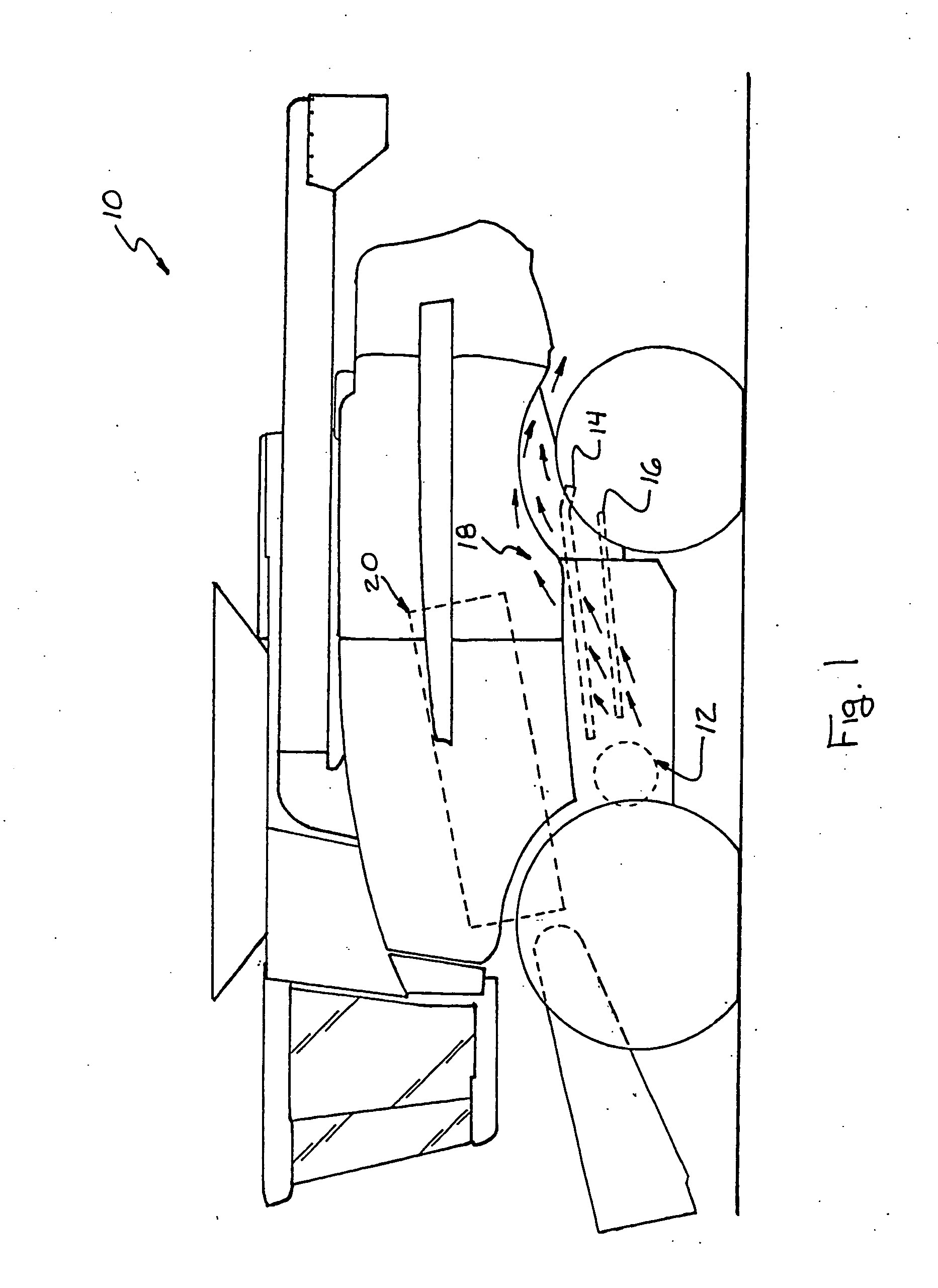
[0013] Referring now to the drawings, in FIG. 1, a representative agricultural combine 10 including a cross flow fan 12 constructed and operable according to the teachings of the present invention, for directing a flow of air, denoted by the arrows, upwardly through sieves 14 and 16 of a cleaning system 18, is shown. Cross flow fan 12 is located in a lower region of a chassis or frame of combine 10, generally beneath a threshing system 20, and the flow of air is directed toward sieves 14 and 16 by guides of sheet metal or other material (not shown) in the well known manner.

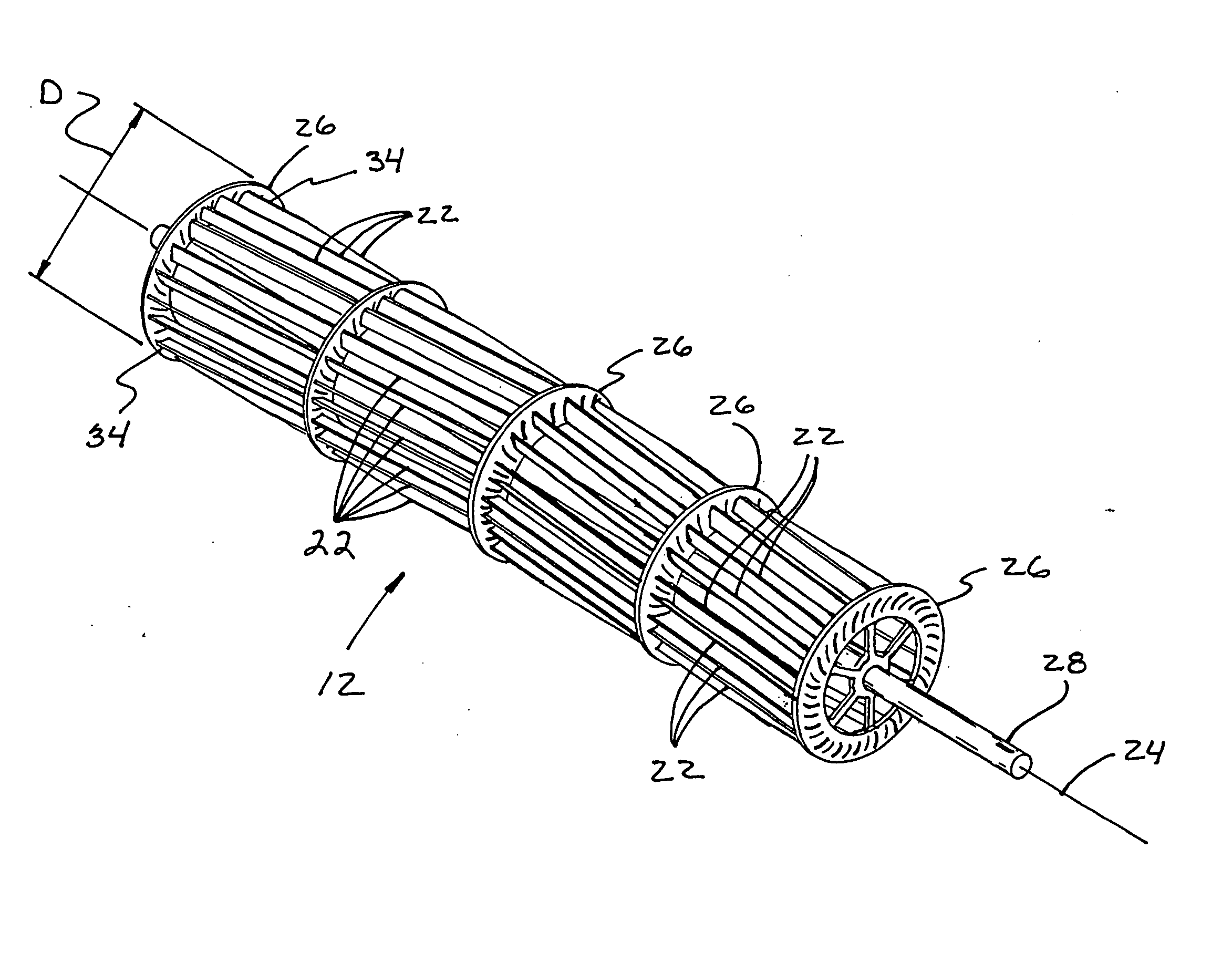
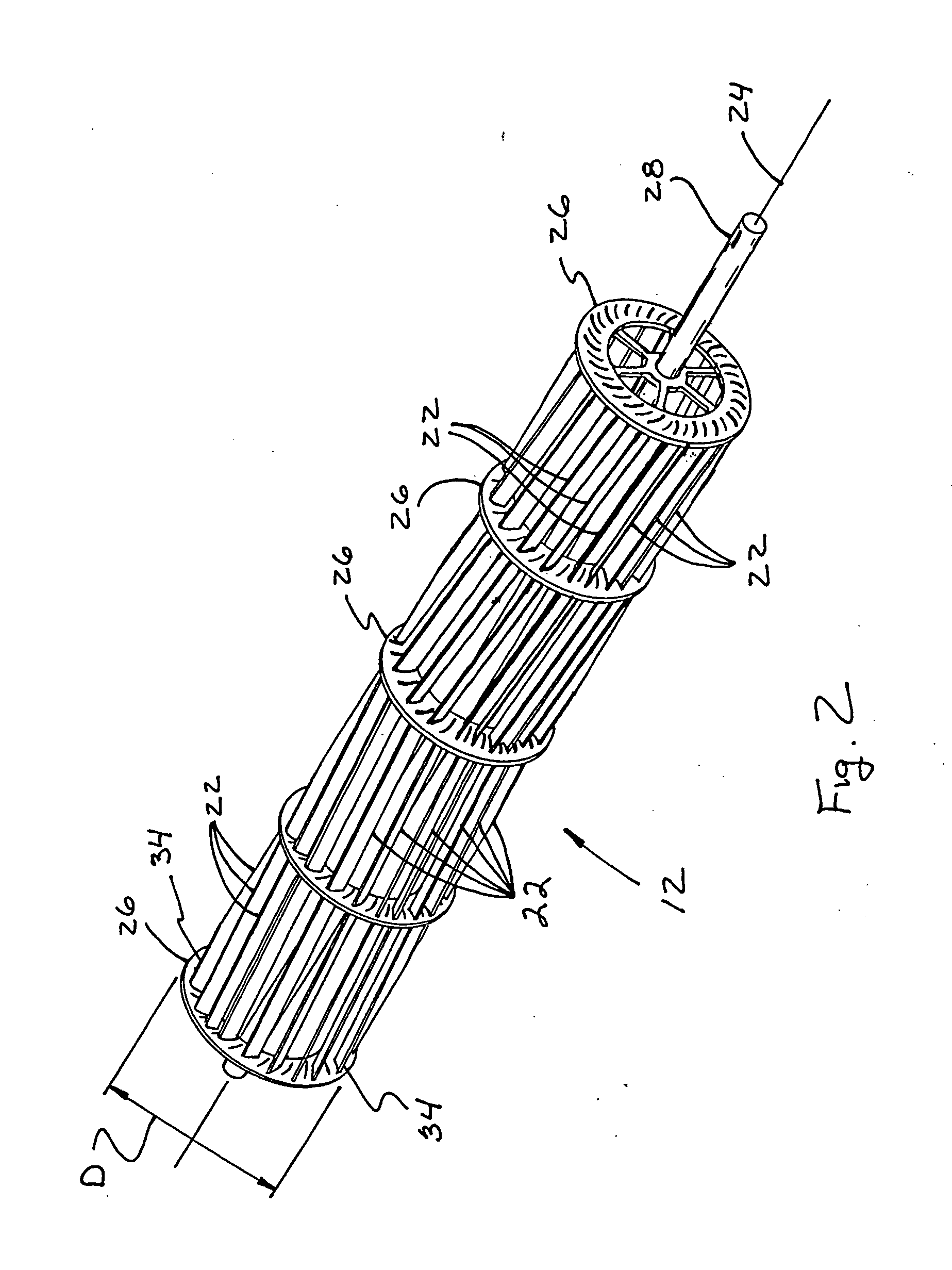
[0014] Referring also to FIG. 2, cross flow fan 12 includes a plurality of elongate fan blades 22 supported and held in an axial cylindrical, skewed pattern about a central rotational axis 24, by a plurality of axially spaced disk shape fan blade mounting members 26, supported on an axially extending shaft 28.

[0015] Referring also to FIG. 3, each fan blade mounting member 26 is preferably of molded construction ...


PUM


Abstract

A fan for a cross flow fan assembly, including a plurality of elongate fan blades supported in an axial cylindrical pattern about a rotational axis by disk shape fan blade mounting members located adjacent ends of the blades. The fan blades have radial outer end portions defining an outer diameter of the fan, radial inner end portions opposite the radial outer end portions, and curved intermediate portions between the radial outer end portions and the radial inner end portions, respectively. Each of the fan blades is oriented such that the radial outer end is at about a 28° angle to a line tangent to the fan diameter at the outer end portion thereof, and the radial inner end portion is directed radially inwardly directly toward the axis or such that a line tangential to the radial inner end portion will pass through the axis.

Description

TECHNICAL FIELD [0001] This invention relates generally to a fan for a cleaning system of an agricultural combine, and more particularly, to a cross or transverse flow fan which provides a relatively high air flow volume at a relatively lower cost than other known cross flow fans for combine cleaning systems. BACKGROUND ART [0002] A typical agricultural combine includes a crop header apparatus which reaps planted grain stalks and then feeds them to a threshing apparatus arranged within a body of the combine. The threshing apparatus functions to separate grain from material other than grain. The grain falls through openings in the threshing apparatus and is directed to a cleaning system also arranged within the combine body. [0003] A typical cleaning system includes oscillating cleaning sieves. The cleaning sieves are located below the threshing apparatus to receive the grain and other materials expelled from the threshing apparatus. The oscillation of the sieves arranges the materia...

Claims


Application Information

Patent Timeline
Patent Type & Authority Applications(United States)
IPC IPC(8): F04D29/28F04D29/30
CPCF04D29/30F04D29/283A01F12/444
Inventor RICKETTS, JONATHAN E.SCHWINN, KEVIN S.WOLTERS, JOSHUA J.
Owner CNH IND AMERICA LLC
Why Eureka
Try Eureka