Baling apparatus

a technology of baling apparatus and baling rod, which is applied in the field of baling rod, can solve the problems of hysteresis loss and the difficulty of safe movement of overlong equipment, and achieve the effect of reducing hysteresis loss

Inactive Publication Date: 2005-01-27
MCDOWELL BRUCE RICHARD
View PDF4 Cites 11 Cited by
  • Summary
  • Abstract
  • Description
  • Claims
  • Application Information

AI Technical Summary

Benefits of technology

[0009] It is therefore an object of the present invention to provide apparatus for forming highly compressed bales which allows the facto

Problems solved by technology

However, many materials have some elasticity, and therefore have hysteresis losses when compacted; to reduce such losses, it is necessary to use a lower compaction pressure for a longer time.
A further factor which must be take

Method used


Image

  • Baling apparatus
  • Baling apparatus
  • Baling apparatus

Examples


Embodiment Construction

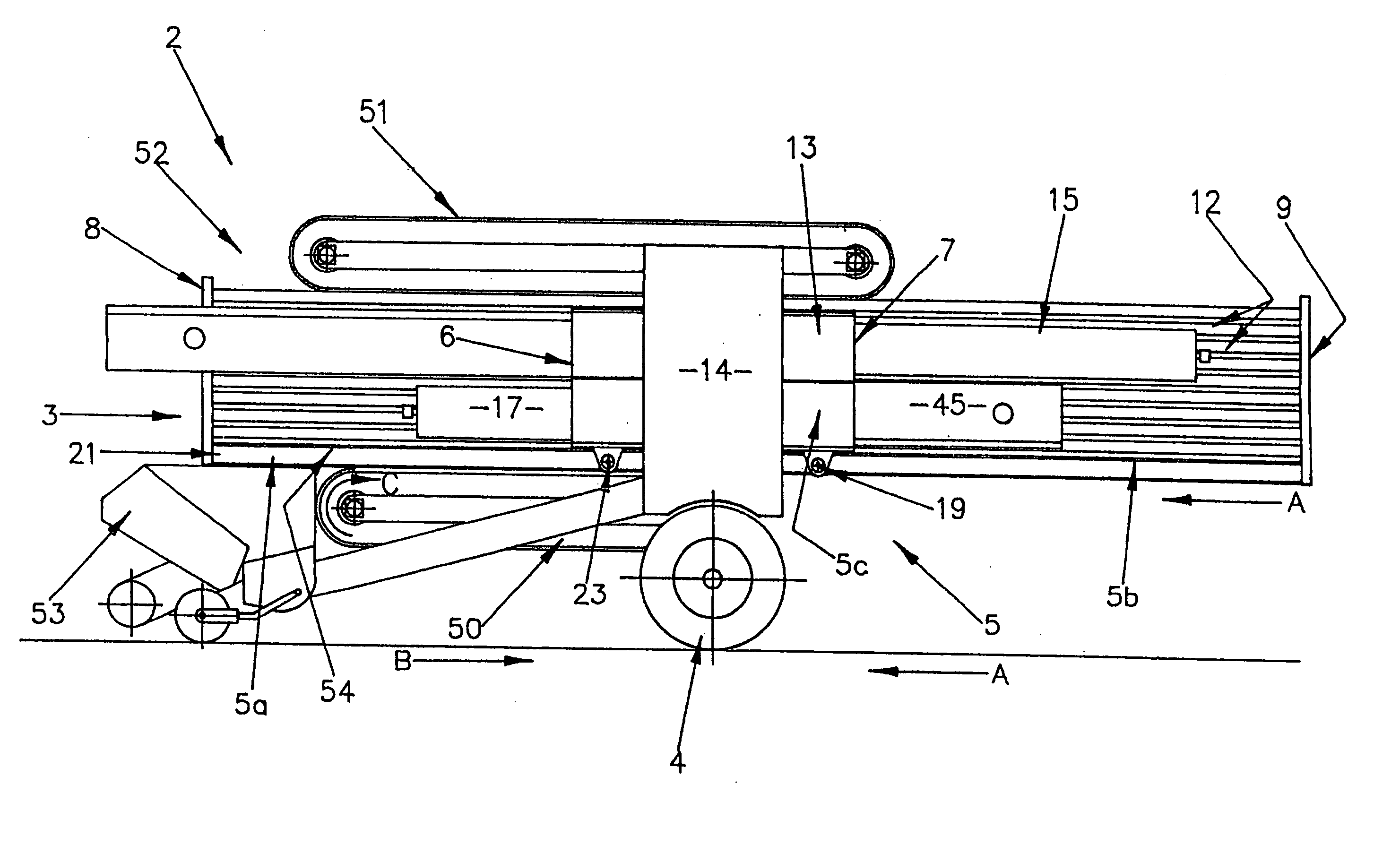
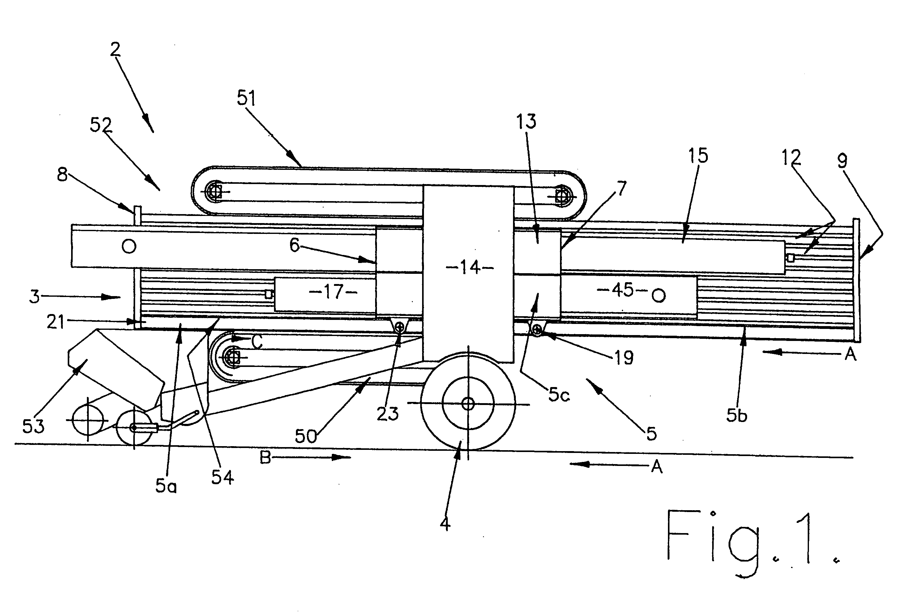
[0026] Referring to FIGS. 1-5 of the drawings, a baling apparatus 2 designed particularly for baling silage or similar fodder is constructed as a trailer unit adapted to be towed by means of a drawbar (not shown) mounted at the front 3 of the apparatus. The apparatus 2 is mounted on a pair of wheels 4.

[0027] The apparatus includes a central bale-forming compression chamber 5 which is fixed in height but which can be altered in length by moving a pair of gates 6, 7, towards or away from each other.

[0028] The forward gate 6 is movable from a position adjacent the forward end 8 to the fully-compressed position shown in FIG. 1. The rear gate 7 is movable from a position adjacent the rear end 9 to the position of FIG. 1. The gates 6, 7, can be moved independently of each other, but usually are moved simultaneously, as hereinafter described.

[0029] The chamber 5 is formed in three sections:—outer sections 5a and 5b and an inner section 5c. All sections are of the same height.

[0030] The...


PUM


Abstract

Baling apparatus (2) for preparing highly compressed bales of materials such as silage, wool, paper, cardboard, plastics materials and scrap metal, the baling apparatus including a compression chamber (5) which includes two opposed gates (6, 7) which can be moved towards or away from each other by moving means (15, 16, 17, 18), to compress material between the gates into a bale; the gates being moved by moving means (15, 16, 18) which are mounted alongside the compression chamber (5).

Description

TECHNICAL FIELD [0001] The present invention relates to apparatus for forming bales of a range of different materials, and in particular to baling apparatus capable of making highly compressed bales. [0002] The apparatus of the present invention is especially well suited to making highly compressed bales of fragmented materials such as silage, hay, straw, wool, rags, paper, cardboard, plastics materials including plastics containers, fibrous waste materials, and scrap metal. [0003] The density of a highly compressed bale varies, depending upon the material in the bale; for a bale of silage (50 percent to 60 percent dry matter) a bulk density of 900 kilograms per cubic metre is typical; for baled scrap cardboard a typical density would be 500 kilograms per cubic metre. BACKGROUND ART [0004] Highly compressed bales have a number of advantages:—they provide compact storage and thus save space; they have better cohesion and are less prone to damage in handling. In the case of bales of s...

Claims


Application Information

Patent Timeline
IPC IPC(8): A01F15/04B30B9/30B65B27/12
CPCA01F15/04B65B27/12B30B9/30B30B9/32
Inventor MCDOWELL, BRUCE RICHARD
Owner MCDOWELL BRUCE RICHARD
Why Eureka
Try Eureka