
Modified shipping container

a technology of shipping containers and modified containers, applied in the field of platform-based freight containers, can solve the problems of sporadically transported freight in non-standard containers, and achieve the effects of low cost, simple construction, and convenient manufacturing, handling and transportation

Inactive Publication Date: 2005-01-27
PHOENICIA AMERICA ISRAEL FLAT GLASS
View PDF13 Cites 8 Cited by
  • Summary
  • Abstract
  • Description
  • Claims
  • Application Information

AI Technical Summary

Benefits of technology

[0016] According to one aspect of the present invention, there is provided a freight-shipping container, combining the advantages of a flatrack, such as ease of loading and collapsibility, with the possibility of side protection of freight, not inferior to the protection provided by an “open top” container. The shipping container combines these advantages based on a standard flatrack, or a flatrack-like shipping container, without requiring modification thereto.
[0023] Forming the side edges of the side walls with U-shaped portions prevents the movement of the side walls, when attached to the flatrack, in any direction other than the direction of sliding. In other words, after a side wall has been attached to the flatrack, by slidingly lowering it onto two associated stanchions along their longitudinal axes, the only way to dissemble them is by sliding raising the side wall.
[0027] Advantages of the shipping container of present invention include inter alia the possibility of side protection of cargo loaded thereon along with ease of loading and unloading at significantly low cost. As the shipping container of the present invention may comprise a standard flatrack, which is a ubiquitous in the shipping industry, the shipper is not limited to an exclusive type of container.
[0028] In accordance with another aspect of the present invention there is provided a side wall for attaching to a standard flatrack, or a flatrack-like container, whether collapsible or not, with no need for modification of either the flatrack or the side wall. The side wall, as described above, is very simply constructed and therefore easy to manufacture, handle and transport and very inexpensive to produce. It is also comparatively lightweight and simple-shaped and can therefore be easily and economically shipped back for reuse.

Problems solved by technology

As discussed hereinbefore, most shipping containers have long been standardized, however, freight may be sporadically transported in non-standardized containers.

Method used


Image

  • Modified shipping container
  • Modified shipping container
  • Modified shipping container

Examples


Embodiment Construction

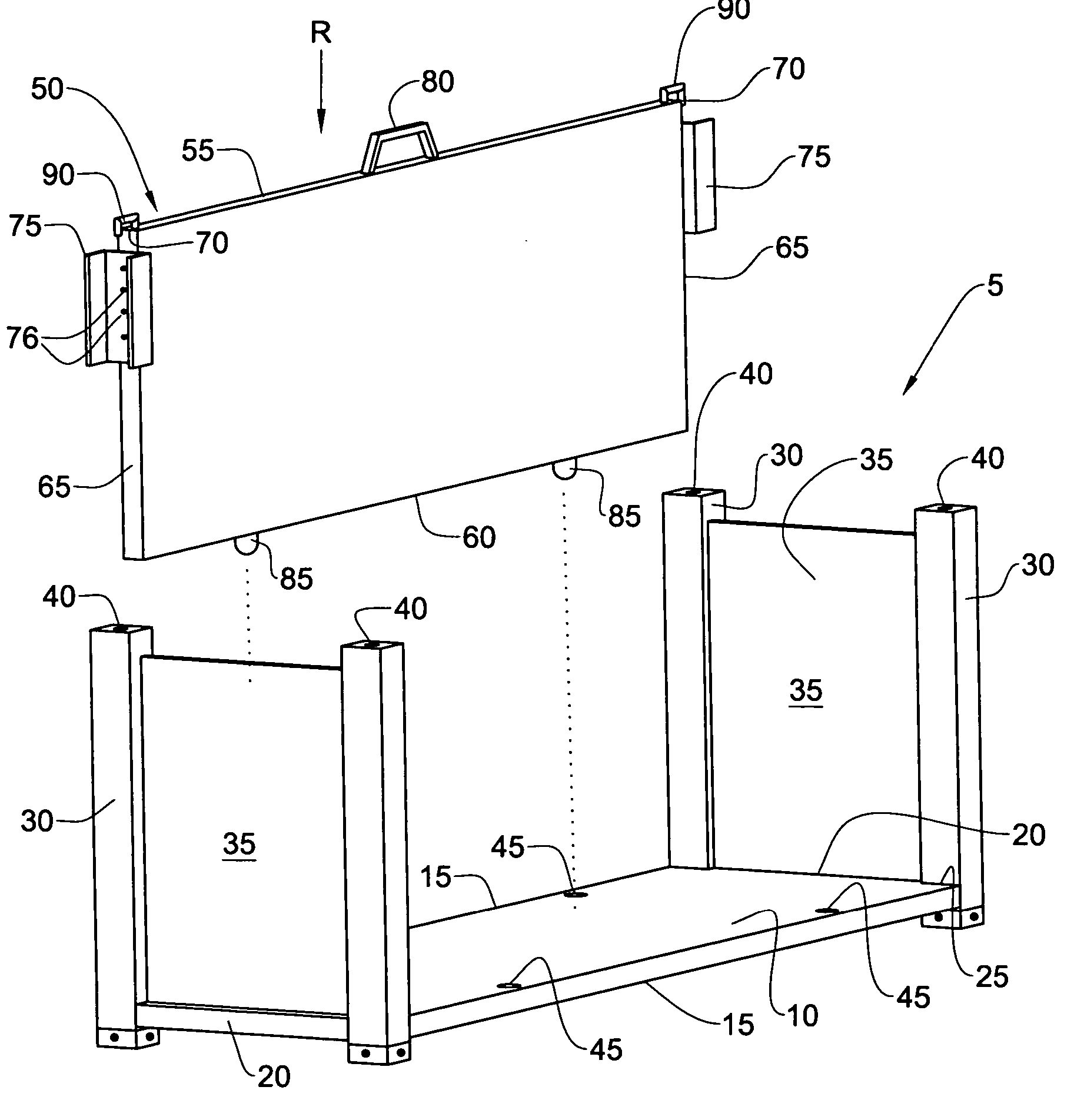
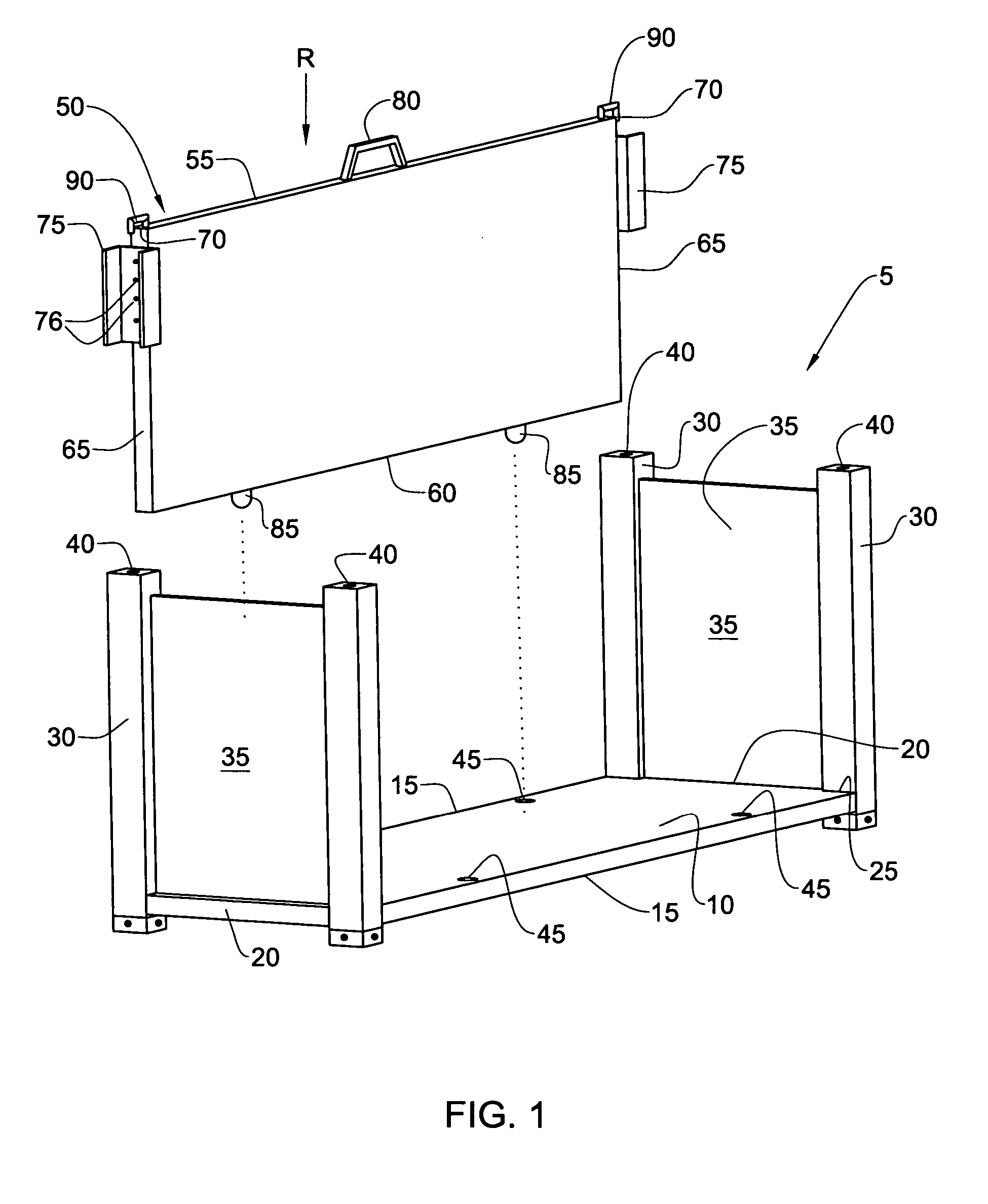
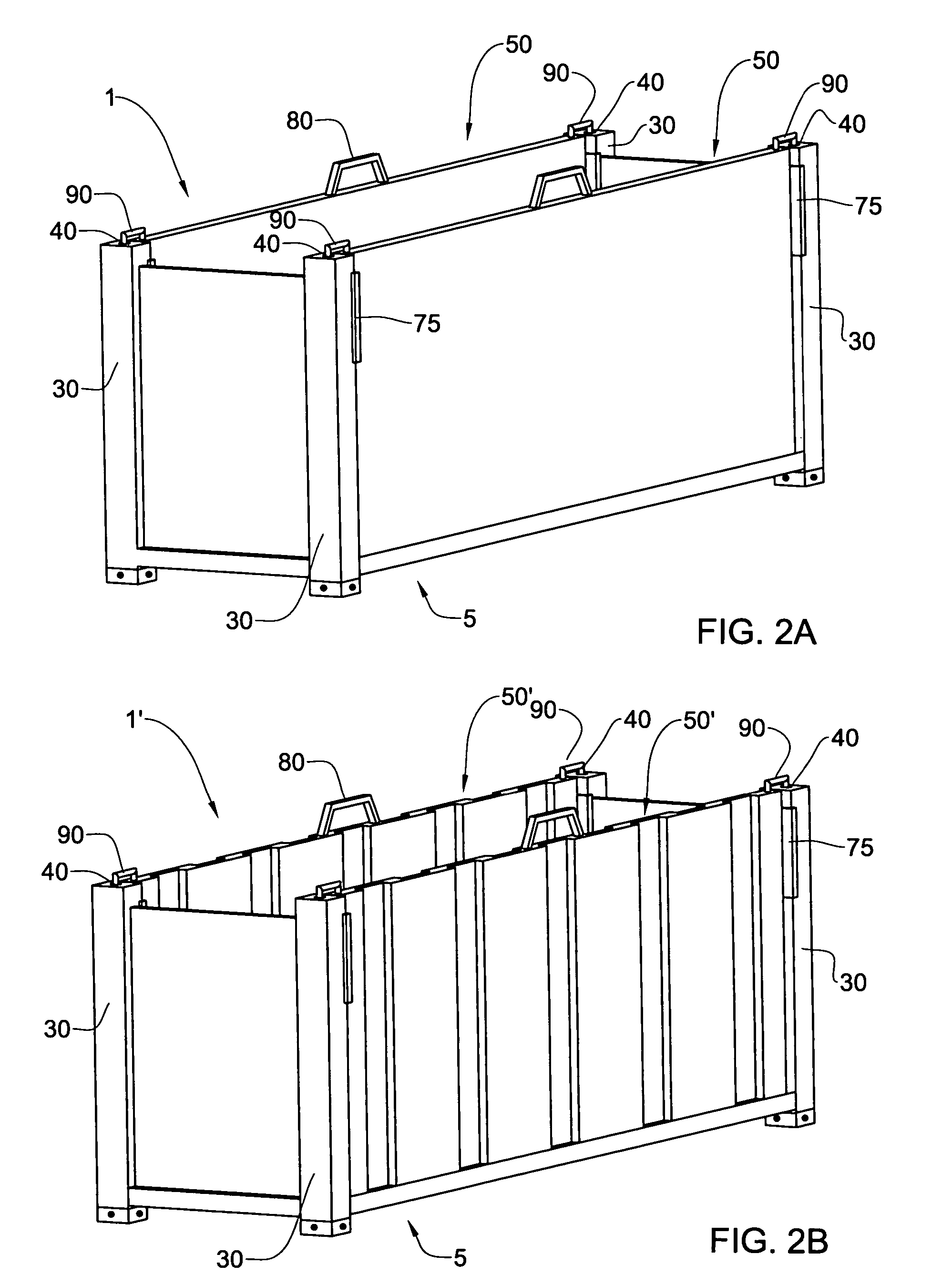
[0035] Referring to FIG. 1, retrofitting a standard flatrack 5 with a detachably attachable side wall 50 is illustrated, to obtain a shipping container 1 according to one embodiment of the present invention as shown in FIG. 2A. FIG. 2B shows a shipping container 1′ according to another embodiment of the present invention, which comprises the same standard flatrack 5 and in which side walls 50′ are corrugated so as to gain strength and rigidity without increasing weight. Since the containers 1 and 1′ are identical in their manner of mounting the side walls 50, 50′ on the flatrack 5, in further description hereinbelow only the container 1 will be referred to.

[0036] The flatrack 5 comprises a rectangular floor 10 having two side edges 15 and two end edges 20 intersecting with the side edges at four corners 25.

[0037] Four vertical stanchions 30 having rectangular cross-section are mounted on the floor 10 at the corners 25 and two vertical end walls 35 extend therebetween along the end...


PUM


Abstract

A shipping container for transporting cargo, comprising a track having a rectangular floor and vertical stanchions mounted at its comers with two opposite end walls extending therebetween, and one or more side walls having side edges with at least a portion corresponding in shape to the stanchions to interact therewith for detachably attaching the, or each, side wall to the track to form a roofless container.

Description

FIELD OF THE INVENTION [0001] This invention relates to freight conveyance containers and in particular, to platform based freight containers. BACKGROUND OF THE INVENTION [0002] Several types of containers for transporting freight on ships, trains, trucks and other long distance transportation means, are known. These shipping containers have long been standardized, and therefore they normally have the same external dimensions so they can be conveniently stored together and stacked on top of one another, for maximum cargo space utilization. [0003] Various types of shipping containers are differentiated by different types of freight to be transferred and the requirements associated therewith. [0004] When the freight is in the form of commodities shipped in bundles, cartons, boxes, loose cargo, bulk, furniture, etc., a so-called “high cube” or “dry van” container is used, namely a parallelepiped container with six rectangular faces and lockable doors in one of the faces, for loading an...

Claims


Application Information

Patent Timeline
Patent Type & Authority Applications(United States)
IPC IPC(8): B65D88/12B65D88/52
CPCB65D88/123B65D88/526B65D88/129
Inventor KATZ, YOAV
Owner PHOENICIA AMERICA ISRAEL FLAT GLASS
Learn More