
Sign illumination light fixture

Inactive Publication Date: 2005-01-27
EVERBRITE
View PDF23 Cites 6 Cited by
  • Summary
  • Abstract
  • Description
  • Claims
  • Application Information

AI Technical Summary

Benefits of technology

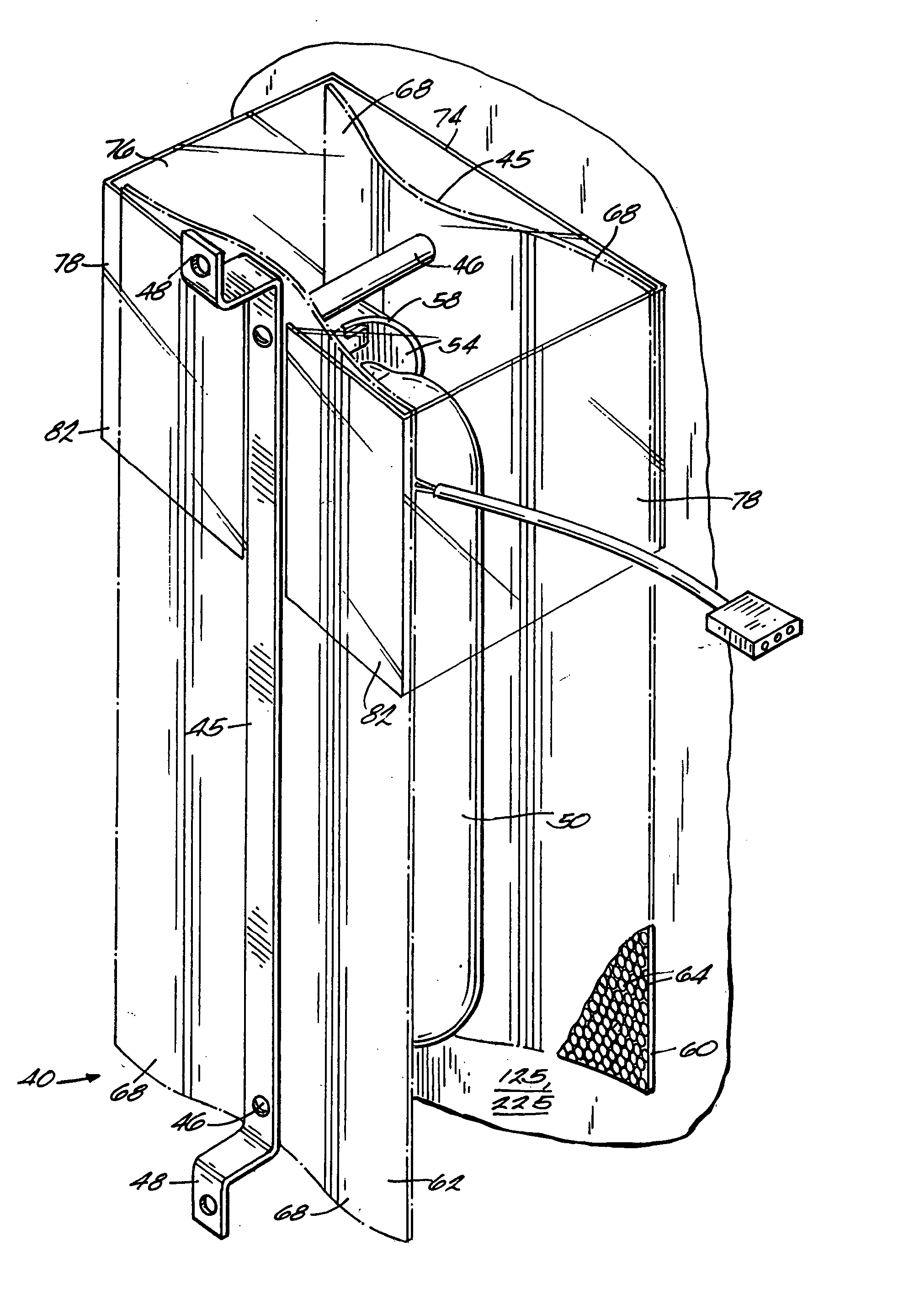
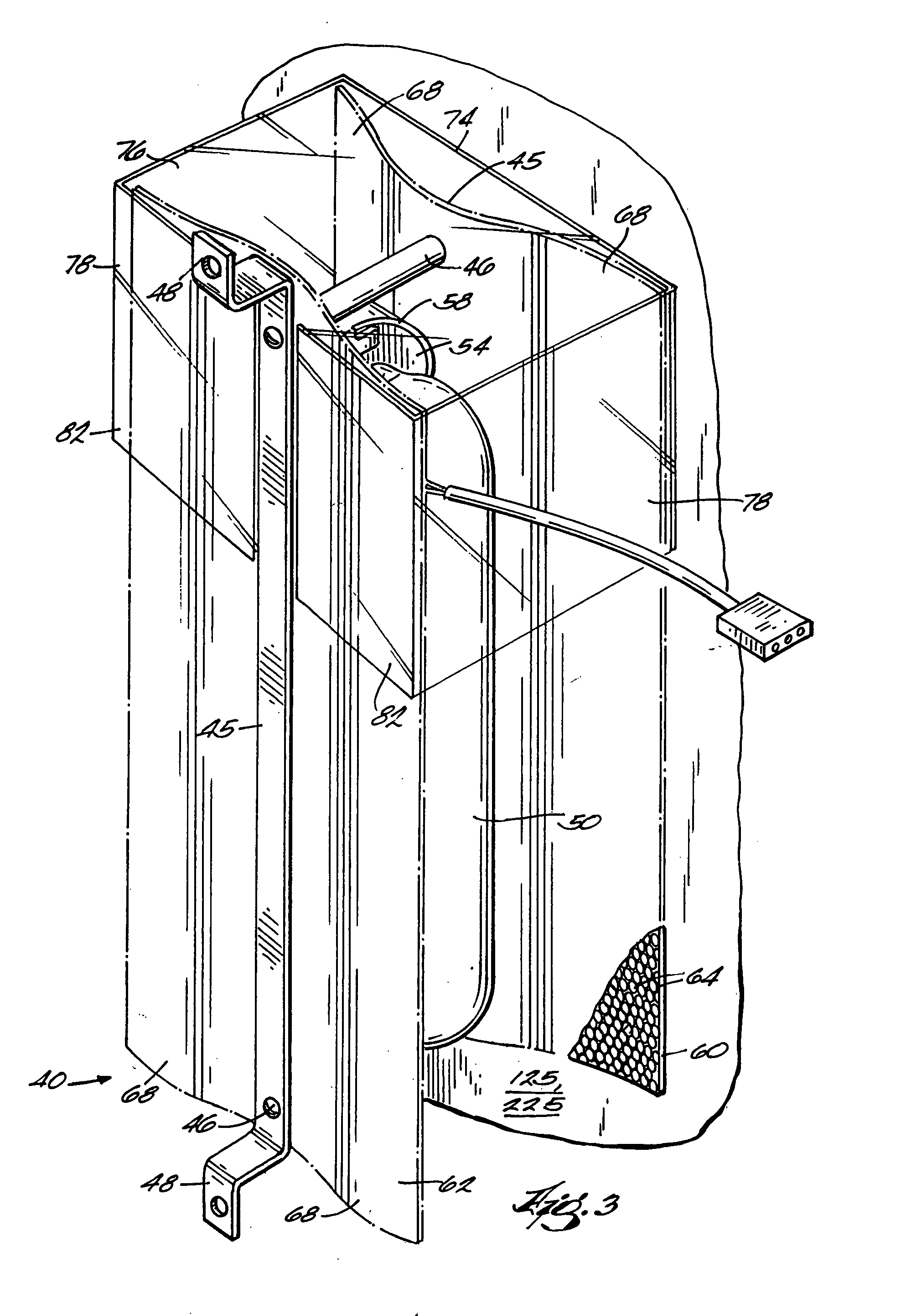
[0006] The present invention provides a light fixture for illuminating a sign. The light fixture according to some embodiments of the present invention has a lamp and one or more reflectors positioned adjacent the lamp to provide for substantially uniform illumination of a sign with a minimum number of light fixtures. One or more of the reflectors may have a predetermined pattern of substantially transparent areas and reflective areas to allow some light to be transmitted through the reflector and to reflect the remainder of the light. In other embodiments, one of the reflectors can be a totally reflective specular reflector. Some embodiments of the light fixture can also include a thermal shield to at least partially prevent thermal convection along some of the lamp in cold ambient temperatures.

Problems solved by technology

Many of these signs, however, are not easily accessible without special equipment.
Thus, if one or more of the lamps used to illuminate the sign were to burn out, it can be quite expensive to change the lamp(s).
Since high reliability lamps need to be changed less often, the added labor and equipment costs to change the lamps occur less often.
However, high reliability lamps are much more expensive than conventional lamps.
Since many lamps are used outdoors, they are subject to temperature extremes.
For example, in some environments the lamp can be subjected to extremely low outdoor air temperatures.
Unfortunately, typical high reliability lamps do not emit as much light in relatively cold temperatures as compared to relatively warm temperatures.
Thus, the added expense of these high reliability lamps may not be practical in some environments due to lack of light emitted in cold temperatures.
On the other hand, high reliability lamps are often compact tubes, which require reflectors to evenly distribute the output light over large areas.

Method used


Image

  • Sign illumination light fixture
  • Sign illumination light fixture
  • Sign illumination light fixture

Examples


Embodiment Construction

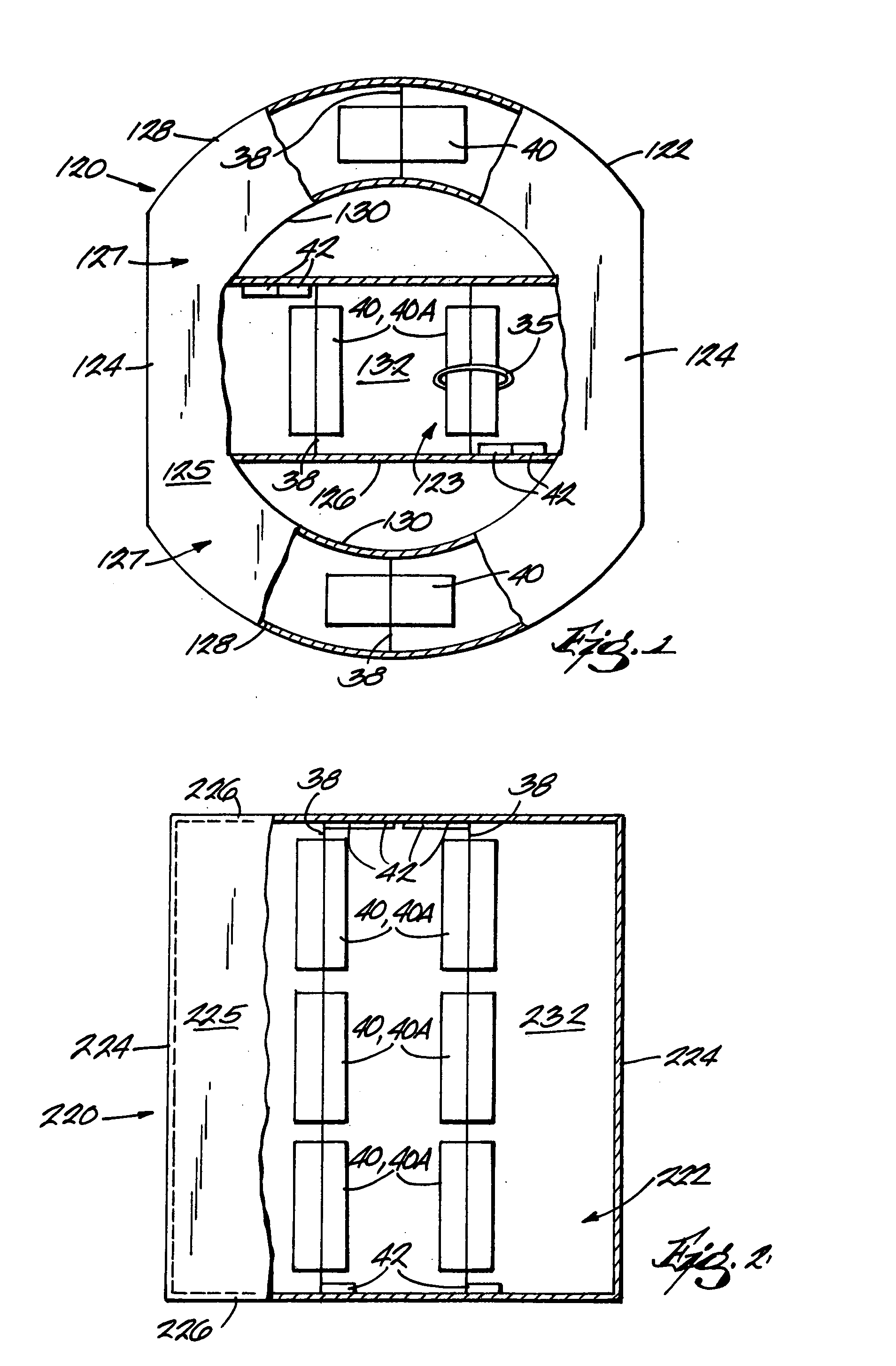
[0025]FIGS. 1 and 2 each illustrate a sign 120, 220 embodying the present invention. The signs 120, 220 each include a housing 122, 222 having at least one output panel (front output panel not shown) and one or more light fixtures 40, 40A (hereinafter “light fixtures” regardless of number) positioned within the housing 122, 222 to illuminate the at least one output panel in a substantially uniform manner.

[0026] The housing 122 shown in FIG. 1 has a rectangular portion 123 and two curved portions 127 located on opposite sides of the rectangular portion 123. The rectangular portion 123 of the housing 122 is defined by opposing sides 124, opposing sides 126, a portion of the back wall 132, and a portion of the front output panel 125 (partially removed). The two curved portions 127 of the housing 122 are defined by a relatively large radius wall 128, a relatively small radius wall 130, a portion of the back wall 132, and a portion of the front output panel 125 (partially removed). The ...


PUM

PropertyMeasurementUnit
Poweraaaaaaaaaa
Densityaaaaaaaaaa
Translucencyaaaaaaaaaa

Abstract

The invention provides a light fixture for illuminating a sign. The light fixture has a lamp and one or more reflectors to provide for substantially uniform illumination of a sign with a minimum number of light fixtures. One or more of the reflectors of some embodiments can formed from a material having predetermined pattern for reflecting and transmitting light from the lamp. For example, the reflectors can be made from a neutral density polymeric material consisting of a translucent or substantially transparent polymeric substrate with a pattern of reflective media disposed on or within the substrate. In some embodiments, one of the reflectors can be a specular reflector. Some embodiments of the light fixture can also include a thermal shield to at least partially prevent thermal convection along a portion of the lamp.

Description

FIELD OF INVENTION [0001] This invention relates generally to light fixtures, and more particularly to light fixtures used to illuminate signs. BACKGROUND OF THE INVENTION [0002] Lamps are used to illuminate signs, such as street signs, billboards, business signs, and the like. Many of these signs, however, are not easily accessible without special equipment. For example, in some instances a lift truck needs to be used to access the sign. Thus, if one or more of the lamps used to illuminate the sign were to burn out, it can be quite expensive to change the lamp(s). [0003] Some lamp manufacturers have recognized this problem and have developed high reliability lamps or bulbs that have substantially longer lives than conventional lamps. For example, these long-life lamps can last about five to ten times longer than conventional lamps. Since high reliability lamps need to be changed less often, the added labor and equipment costs to change the lamps occur less often. However, high reli...

Claims


Application Information

Patent Timeline
IPC IPC(8): F21V7/00F21V7/22F21V23/02F21V25/00F21V29/15G09F13/04G09F13/14
CPCF21V7/0016F21V7/005F21V7/22F21V23/02F21V29/15G09F13/04G09F13/14Y10S362/812F21V25/00F21V7/24F21V7/28
Inventor MOHACSI, FERENC
Owner EVERBRITE
Learn More