Eureka AIR delivers breakthrough ideas for toughest innovation challenges, trusted by R&D personnel around the world.

Blind rivet with steal

Inactive Publication Date: 2005-01-27
NEWFREY
View PDF9 Cites 9 Cited by
  • Summary
  • Abstract
  • Description
  • Claims
  • Application Information

AI Technical Summary

Benefits of technology

[0015]FIG. 4a is a sectional view of a

Problems solved by technology

It is generally understood that whilst the mandrel head is drawn into the rivet, to deform the rivet when set, such engagement between the rivet head and the rivet is not airtight nor waterproof.
However, the manufacture of closed-end blind rivets is comparatively more complex and expensive whereby the large mandrel head is first received in a cup shaped preform, the resulting subassembly extruded to encapsulate the mandrel within the body of the rivet and simultaneously form the rivet body flange.
Not only is this process more expensive but requires a high degree of tooling accuracy and manufacturing skill to prevent damage to the mandrel and the associated manufacturing tooling.
A further drawback to this type of manufactured blind rivet is a limitation to the length of the rivet body and / or the length of the mandrel that can be made on current manufacturing machinery and if suitable machinery were available the cost of that machinery plus the attendant slowness of the process would render the resulting closed end rivet prohibitively expensive.
However, where such rivets are required to secure thick workpieces or where the rivet is inserted into narrow recesses or channels difficulties can arise due to the limitation of the length of the rivet body or the length of the mandrel thus restricting the applicability of closed-end rivets in such applications.
Thus current technology does not provide for blind rivets capable of application in deep narrow recesses or thick joints and being able to consistently achieve a watertight or airtight seal.

Method used


Image

  • Blind rivet with steal
  • Blind rivet with steal
  • Blind rivet with steal

Examples


Embodiment Construction

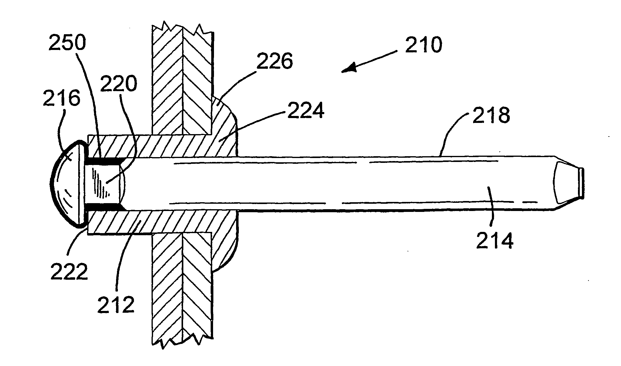
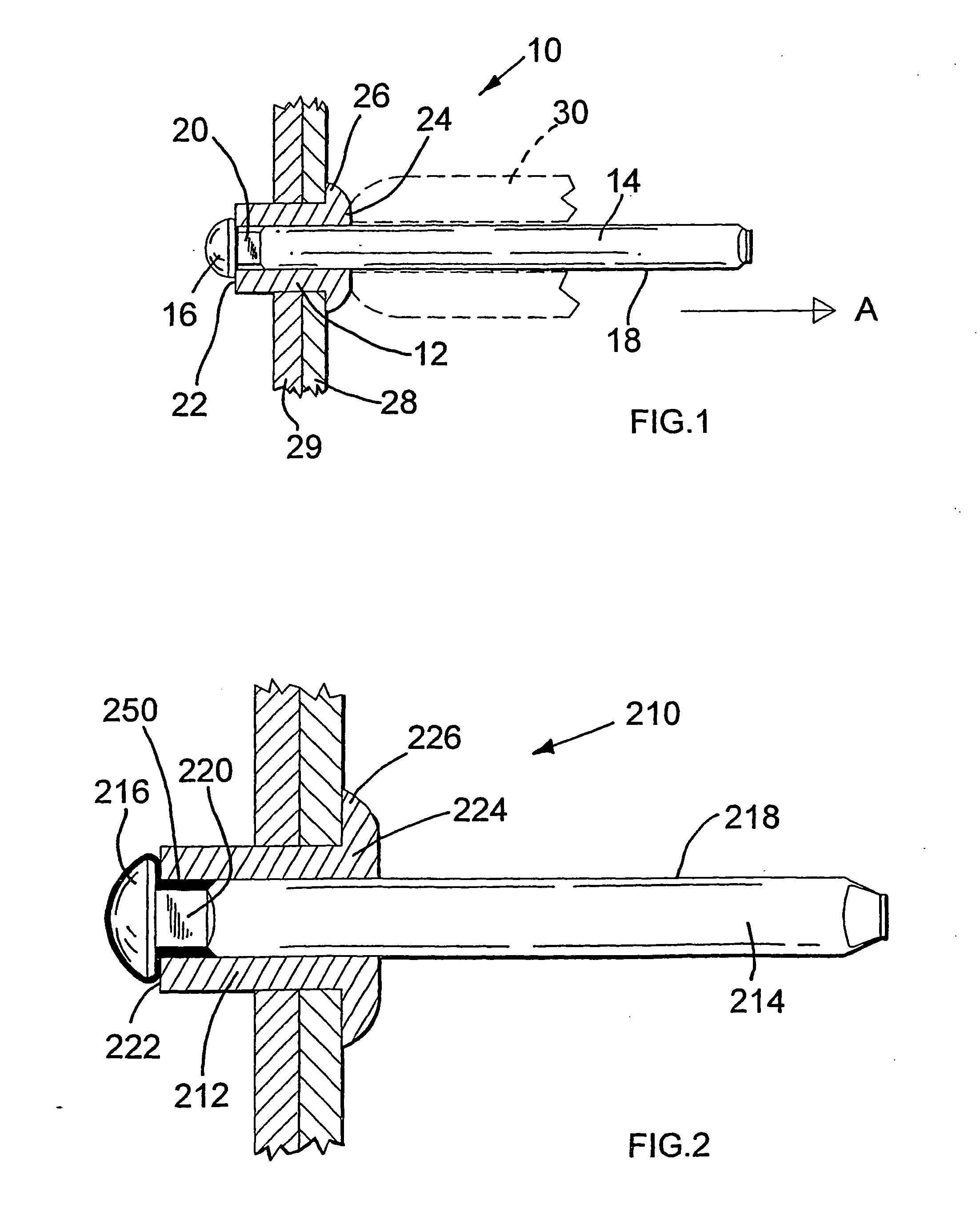
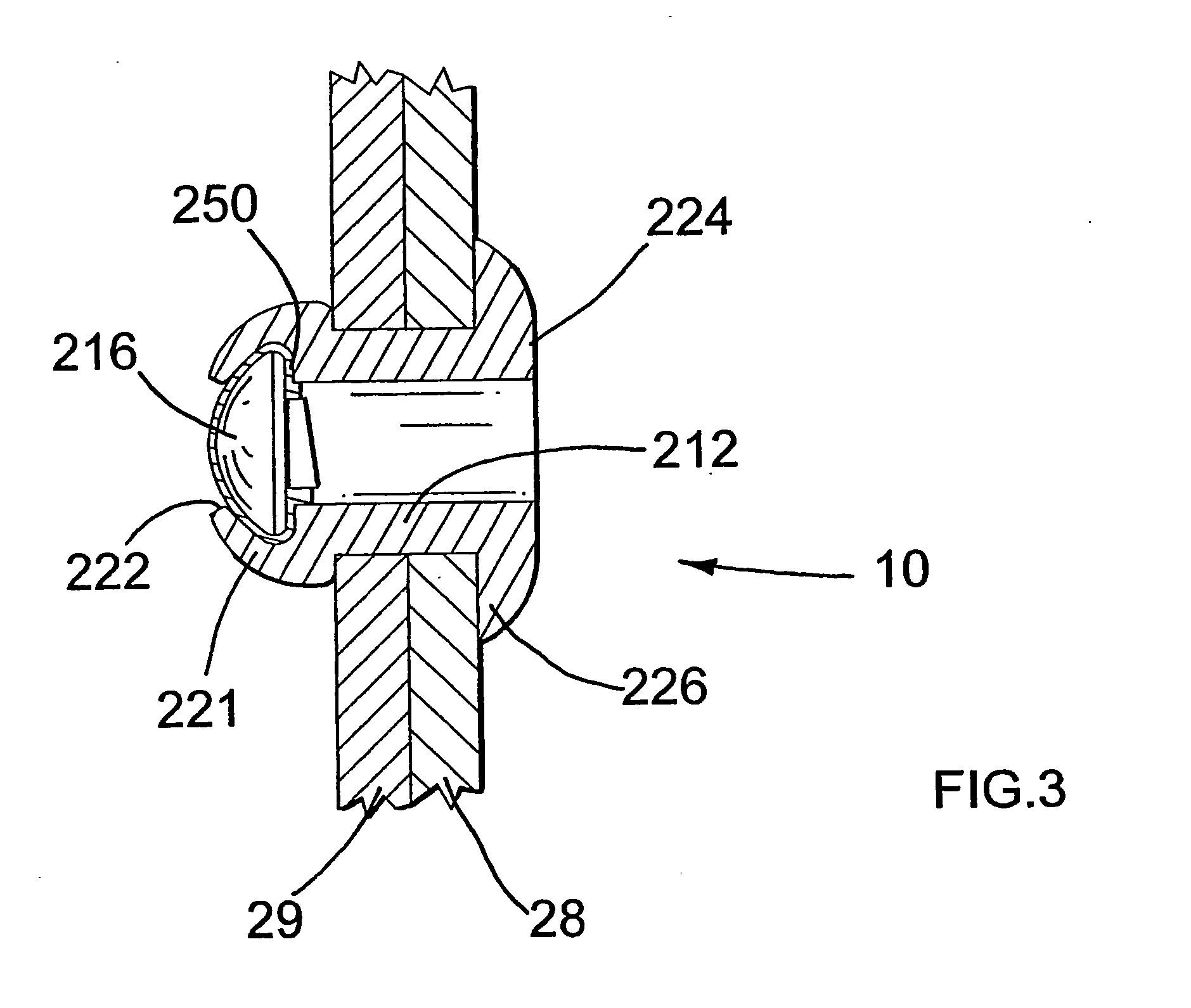
[0017] Referring now to FIG. 1, a conventional open-end blind rivet 10 comprises a substantially hollow tubular rivet body 12 and an associated mandrel 14. The mandrel is substantially an elongate cylindrical metal wire (although alternative embodiments for plastics rivets could employ plastics mandrels) having disposed at one end and coaxial therewith, a mandrel head 16 having a diameter greater than the mandrel wire. Disposed between the main body 18 of the mandrel 14 and the mandrel head 16 is a mandrel shank 20, again coaxial with body 18 but having a diameter less than then the diameter of the body 18. Thus the mandrel shank provides a narrowed neck portion of the mandrel as clearly seen in FIG. 1.

[0018] The cylindrical rivet body 12 has an inner diameter substantially equal to the diameter of the mandrel body 18 whereby the mandrel 18 can be fed through the rivet body 12 (in a direction substantially shown by arrow A in FIG. 1) until the head 16 engages with an end surface 22...


PUM


Abstract

An open-end blind rivet (210) comprises a headed mandrel (218) with a substantially tubular rivet mounted thereon with a flowable sealant (250) disposed between the mandrel and the rivet whereby setting of the blind rivet compresses the sealant between the head (216) of the mandrel and an inner surface of the rivet to form a seal therebetween.

Description

BACKGROUND OF THE INVENTION [0001] This invention relates to tubular rivets of the type usually used for holding together two or more sheets of material. More particularly, this invention is directed to an open end blind rivet of the type having a first flange at one end of the rivet body and utilising a headed mandrel to deform the opposed end of the rivet body to compress the sheet material between the flange of the rivet body and its deformed end. [0002] Open end blind rivets are well known and notably those sold under the applicants trade mark POP® (registered trade mark of Emhart Inc.) as a conventional fixing mechanism for holding together two or more sheets of material. This type of blind rivet comprises of a hollow, tubular rivet body having a large flange towards one end thereof to engage with one side of a sheet material, whereby the opposed end of the tubular rivet body is passed through a preformed hole. The rivet further comprises a headed mandrel which extends through ...

Claims


Application Information

Patent Timeline
IPC IPC(8): F16B19/00F16B19/10
CPCF16B19/1054F16B19/008
Inventor JONES, STEVEN V.
Owner NEWFREY
Why Eureka
Eureka Blog
Learn More