

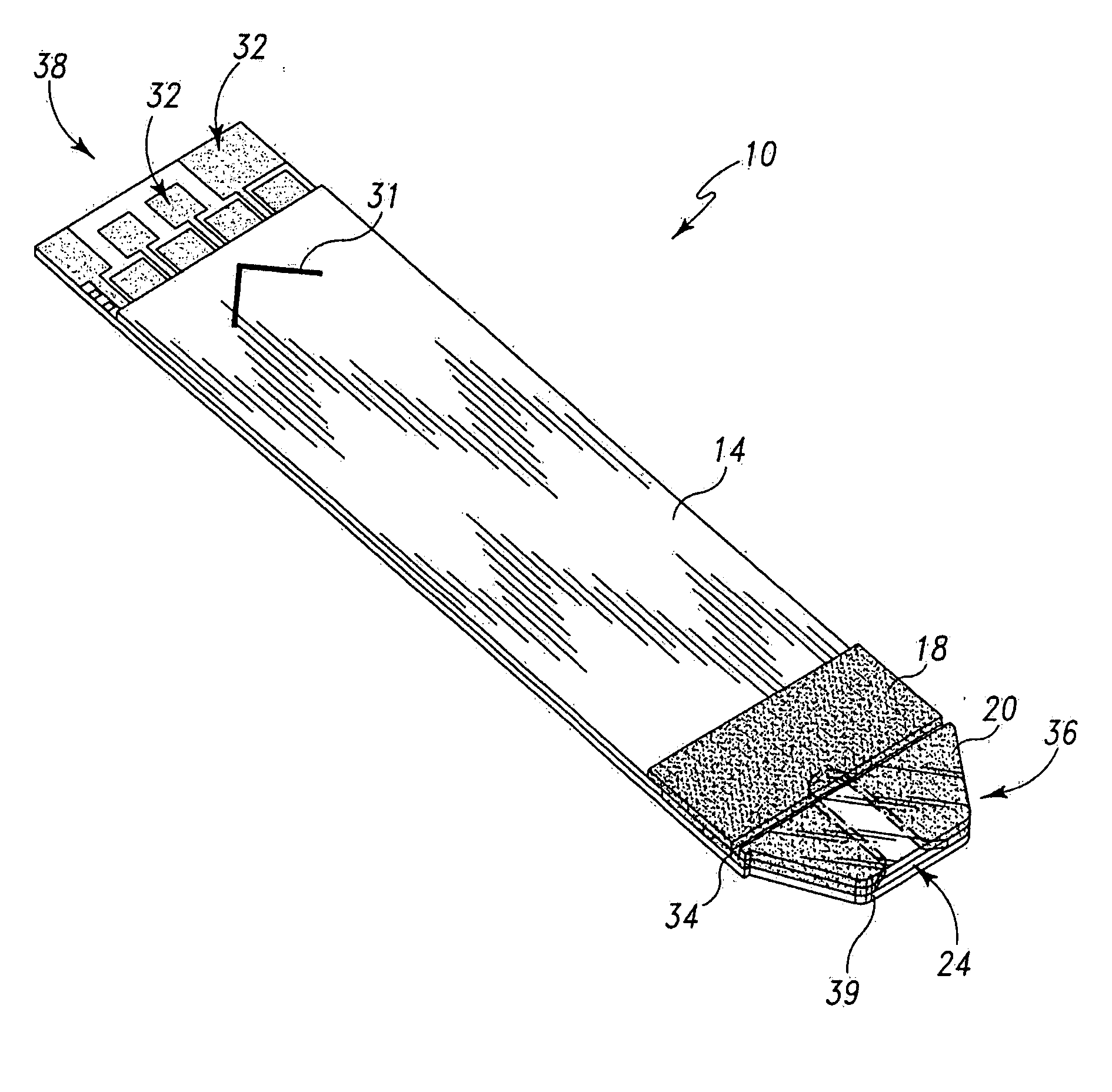
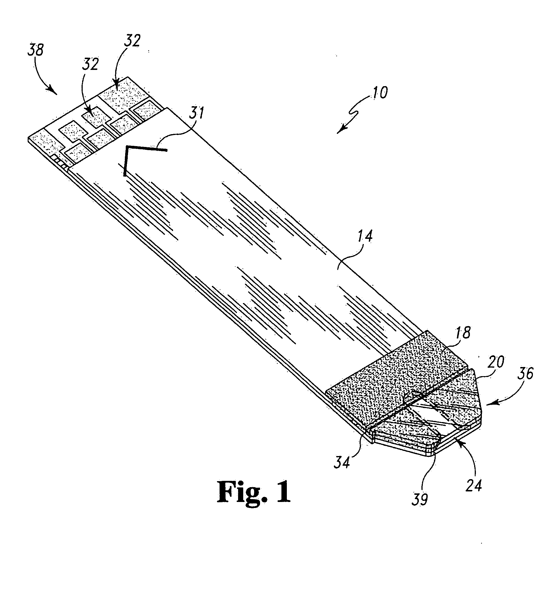
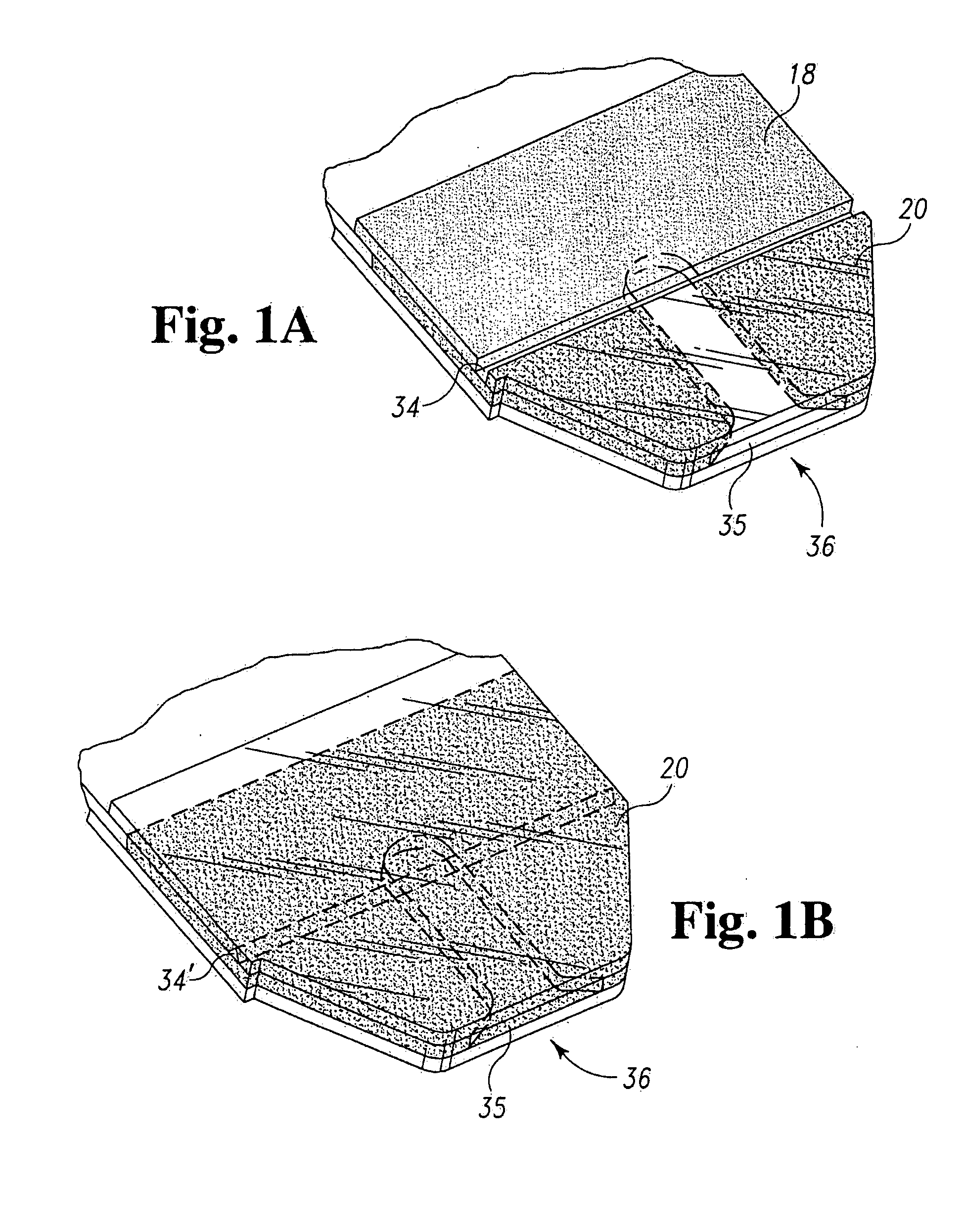
Test strip with flared sample receiving chamber
a sample receiving chamber and test strip technology, applied in the field of body fluid testing, can solve the problems of difficult for this segment to accurately align their fingers, and difficulty in accurately applying (or “targeting”) a small sample volume to the capillary of the test strip, so as to reduce dose hesitation, promote sample wicking, and reduce dose hesitation
- Summary
- Abstract
- Description
- Claims
- Application Information
AI Technical Summary
Benefits of technology
Problems solved by technology
Method used
Image

Examples
example
By way of specific example, a test strip is formed based on the described method and using materials as follows. The bottom substrate is surface coated with a 50 nm layer of gold, and is slit to widths of 43-45 mm. Laser ablation (308 nm) is performed using a field size of approximately 40 mm×10 mm. The spacing layer assembly includes a spacing layer film of white Melinex™ 339, and a thickness of 0.1016 or 0.127 mm (4 or 5 mil). The bottom and top adhesives are an Adhesive Research Arcare 90132 adhesive at 0.0254 or 0.0127 mm (1 or ½ mil), sandwiched between release liners having a thickness of 0.0508 mm (2 mil). The capillary channels are formed with a width of 1.500 mm, + / −0.050 mm, and a pitch (spacing) of 9 mm, + / −0.150 mm.
The body cover 18 comprises a strip of Melinex 454, 453 or 339 material, 0.127 mm (5 mil) thick. The chamber cover 20 comprises a polyester or polyethylene naphthate material formed, for example, from Melinex 454 or 453, 0.1016 mm (4 mil) thick. As indicate...
PUM
| Property | Measurement | Unit |
|---|---|---|
| volume | aaaaa | aaaaa |
| volume | aaaaa | aaaaa |
| width | aaaaa | aaaaa |
Abstract
Description
Claims
Application Information