Intra-oral imaging system

a three-dimensional image and imaging system technology, applied in the field of three-dimensional imaging of objects, can solve the problems of little or no feedback, and achieve the effect of reducing the effect of relative motion or eliminating the effect of relative motion

Inactive Publication Date: 2005-01-27
D4D TECH LP
View PDF99 Cites 66 Cited by
  • Summary
  • Abstract
  • Description
  • Claims
  • Application Information

AI Technical Summary

Benefits of technology

[0014] The intra-oral probe may include a multi-dimensional tracking device such as a 3D tracking device. A 3D location of the probe may be transmitted to a controller to track the orientation and location of the probe. A 3D visualization of an image of the object may be displayed to the operator so that the operator can view the image over at least a portion of the actual object being digitized. The operator may progressively digitize portions of the surface of the object including various surface patches. Each portion or patch may be captured in a sufficiently brief time period to eliminate, or substantially reduce, effects of relative motion between the intra-oral probe and the object.
[0015] Overlapping data between patches and a 3D localization relationship between patches may be determined based on the localization information received from the tracking sensor and the HMD position sens

Problems solved by technology

In addition, there may be little or no feedback as to

Method used


Image

  • Intra-oral imaging system
  • Intra-oral imaging system
  • Intra-oral imaging system

Examples


second embodiment

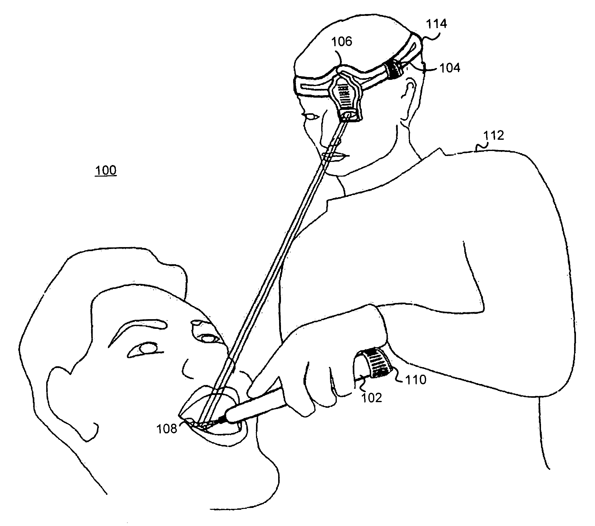
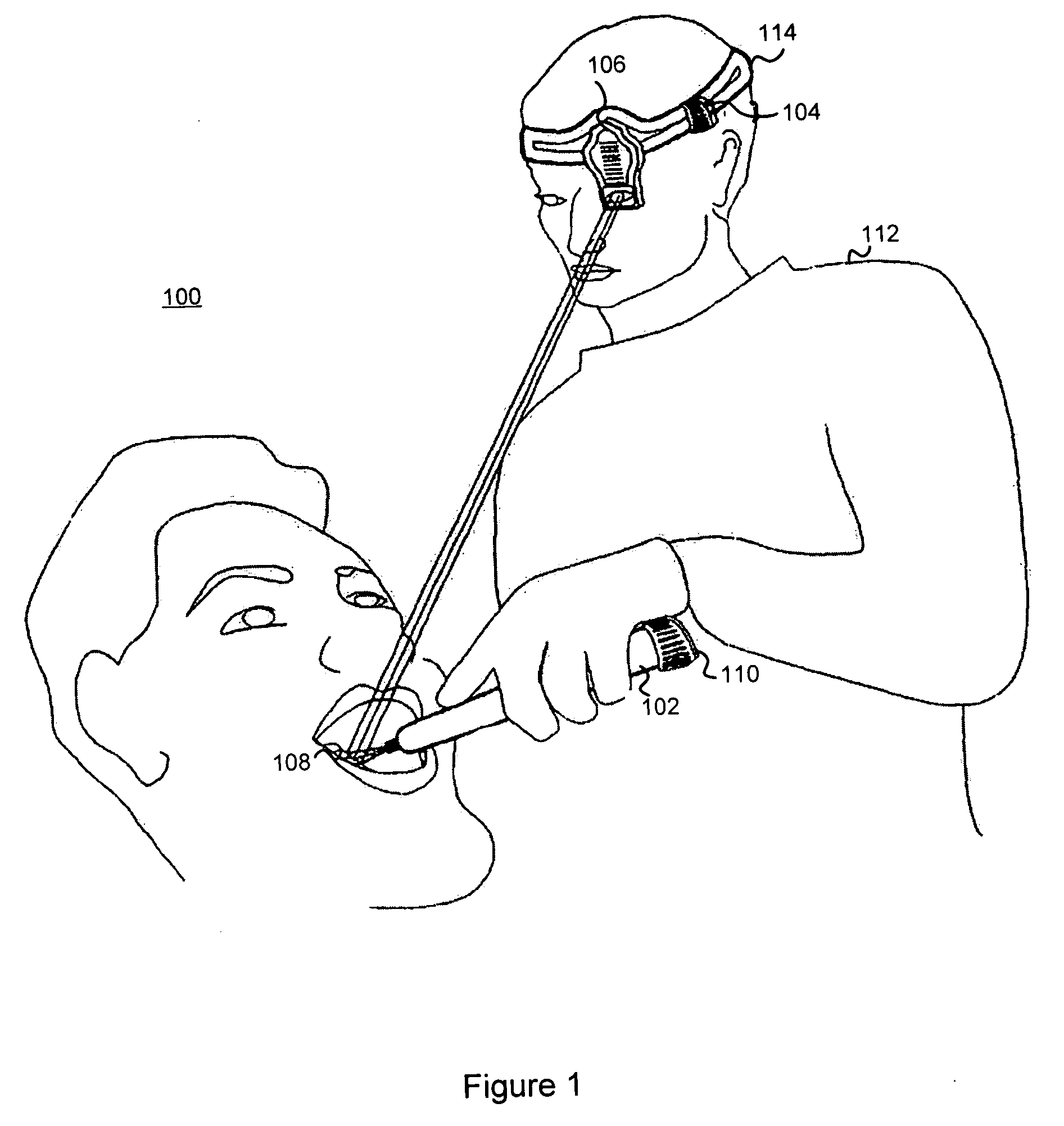
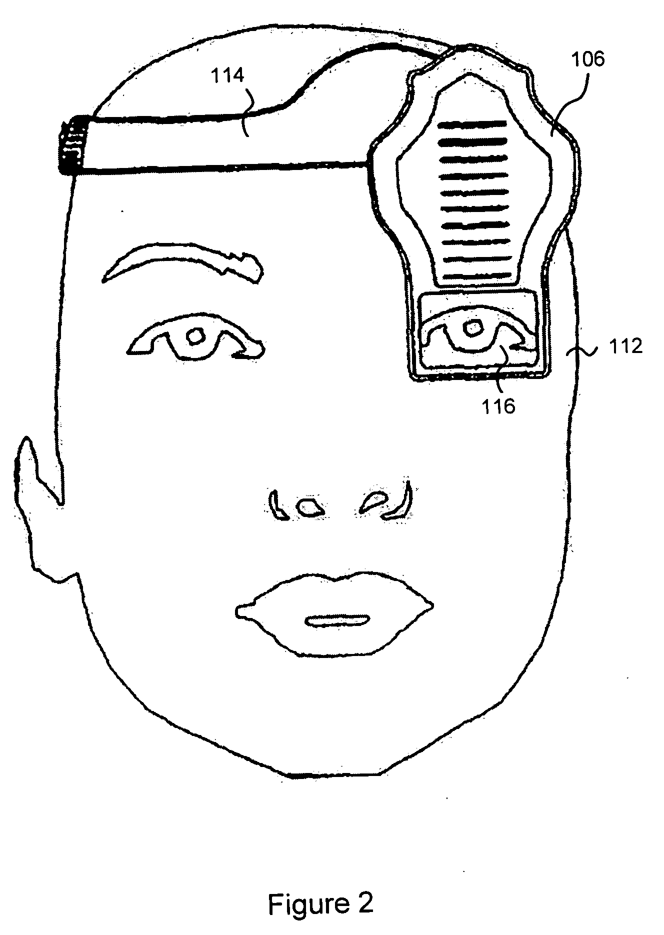
[0033] In a second embodiment, a headband 114 is used to position the HMD 106 on the operator's head so that the screen 116 is in the field of view of the operator 112. The screen may be positioned in front of, or before, at least one of the operator's eyes. The processor 104 also may be affixed to the headband 114. In one embodiment with the processor 104 coupled to the headband 114, the headband 114 may provide a channel for routing wires between the processor 114 and the HMD 106.

third embodiment

[0034] In a third embodiment, the intra-oral imaging system 100 includes an eye tracking sensor 118. FIG. 3 illustrates a side view of the HMD 106 worn by an operator 112 having an eye tracking sensor 118. The eye tracking sensor 118 may be affixed to the HMD 106. The eye tracking sensor 118 may be coupled to or a unitary part of the HMD 106.

[0035] The eye tracking sensor 118 may track or detect movement, location, orientation of the operator's eye 122. By tracking the operator's eye 122, the eye tracking sensor may provide feedback on the operator's line of vision. The eye tracking sensor 118 may also detect the operator's line of vision with respect to an object 108 or with respect to the operator's environment. The eye tracking sensor 118 provides a signal to the processor 104 corresponding to operator's line of sight. The processor 104 receive the signal from the eye tracking sensor 118 and may store the position and view of the eye 112 to the image displayed on the screen 116. ...


PUM


Abstract

A digitized image of a tangible object is displayed in an operator's field of view of the object almost simultaneously as the digitized image is being captured. The image is projected onto a screen in an orientation, position and scale corresponding to an orientation and position of the object within the field of view of the operator so as to be perceived as an overlay to the object. The image may be a one-, two, three, or other multi-dimensional representation of the object and may be captured by an imaging system, such as an intra-oral imaging device.

Description

PRIORITY AND CROSS-REFERENCE TO RELATED APPLICATIONS [0001] This application claims the benefit under 35 U.S.C. § 119(e) of co-pending provisional application No. 60 / 466,549 filed on Apr. 30, 2003, for Digitizing / Imaging System with Head-Mounted Display For Dental Applications, which is incorporated in its entirety herein by reference.BACKGROUND OF THE INVENTION [0002] 1. Related Field [0003] The invention relates to three-dimensional imaging of objects. In particular, the invention relates to displaying a three-dimensional image of an intra-oral (in vivo) dental item that may include dentition, prepared dentition, restorations, impression materials and the like. [0004] 2. Description of the Related Art [0005] Existing intra-oral imaging systems may use a Moiré imaging technique. With Moiré imaging, a three-dimensional (“3D”) image of a physical object may be generated by scanning the object with white light. The 3D image may be viewed on a display or video monitor. Operators may ev...

Claims


Application Information

Patent Timeline
IPC IPC(8): A61B1/24G02B27/00G02B27/01
CPCA61B1/00048A61B1/24G02B2027/0187G02B2027/0138G02B27/017
Inventor QUADLING, HENLEYQUADLING, MARK
Owner D4D TECH LP
Why Eureka
Try Eureka