Apnea/hypopnea detection system and method

a detection system and apnea technology, applied in the field of apnea/hypopnea detection system, can solve the problems of sleep apnea sufferers being at risk for excessive mortality, sleep fragmentation, and possible severe degrees of oxyhemoglobin desaturation, and achieve high-precision measurement of patient flow and accurate a/h detection

a detection system and apnea technology, applied in the field of apnea/hypopnea detection system, can solve the problems of sleep apnea sufferers being at risk for excessive mortality, sleep fragmentation, and possible severe degrees of oxyhemoglobin desaturation, and achieve high-precision measurement of patient flow and accurate a/h detection

US20050020932A1Active Publication Date: 2005-01-27RIC INVESTMENTS LLC

Image

  • Apnea/hypopnea detection system and method
  • Apnea/hypopnea detection system and method
  • Apnea/hypopnea detection system and method

Examples


Embodiment Construction

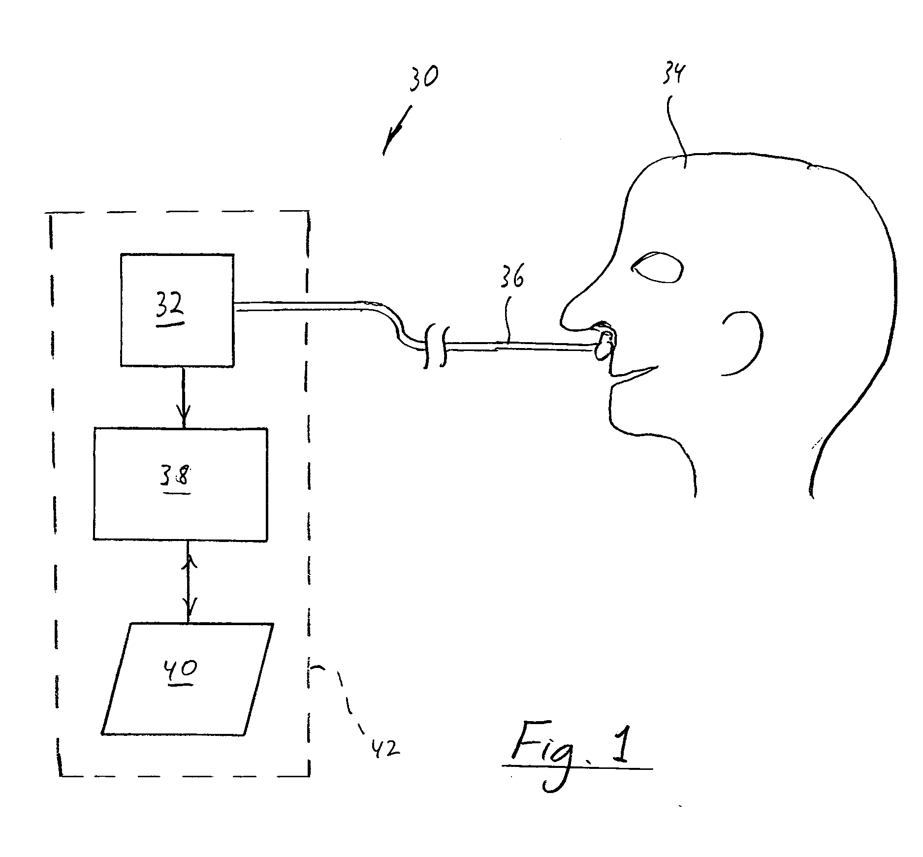
FIG. 1 schematically illustrates an exemplary embodiment of an apnea / hypopnea (A / H) detection system 30 according to the principles of the present invention. In its most basic form, detection system includes a sensor 32 in communication with the airway of a patient 34 to measure the flow of gas into and out of the patient, which is referred to as respiratory flow. In the illustrated embodiment, sensor 32 is a conventional flow sensor, such as a differential pressure sensor that communicates with the airway of the patient via a nasal cannula 36.

It is to be understood that the present invention contemplates using any conventional technique for detecting the patient's respiratory flow. For example, the present invention contemplates using the flow sensing technology taught in U.S. Pat. Nos. 6,017,315; 6,342,040; and 6,554,192 all to Starr et al. The present invention also contemplates using a conventional flow sensor, such as a pneumotach, coupled to the patient's airway via a patient...


PUM


Abstract

An apnea / hypopnea detection system and method that monitors a patient's respiratory flow, determines (a) a long term RMS energy based on the flow, (b) a long term threshold determined based on the long term RMS energy, and (c) a short term RMS energy based on the flow. Determining whether the patient is experiencing an apnea / hypopnea is accomplished by comparing the short term RMS energy with the long term threshold. This A / H detection technique is useful in diagnosing a patient for a breathing disorder, such as OSA, and / or for controlling an auto-titration pressure support system.

Description

BACKGROUND OF THE INVENTION 1. Field of the Invention The present invention pertains to a system and method for detecting apnea / hypopnea events, and, in particular, to an apnea / hypopnea detection technique based on comparing a root-mean-square (RMS) of a patient's respiratory flow to a target value. 2. Description of the Related Art Many individuals suffer from disordered breathing during sleep. Sleep apnea is a common example of such disordered breathing suffered by millions of people throughout the world. One type of sleep apnea is obstructive sleep apnea (OSA), which is a condition in which sleep is repeatedly interrupted by an inability to breathe due to an obstruction of the airway; typically the upper airway or pharyngeal area. Obstruction of the airway is generally believed to be due, at least in part, to a general relaxation of the muscles which stabilize the upper airway segment, thereby allowing the tissues to collapse the airway. Another type of sleep apnea syndrome i...

Claims


Application Information

Patent Timeline
27 Jan 2005
Publication
US20050020932A1
IPC
A61B5/087
CPC
A61B5/4818; A61B5/087
Inventors
HABERLAND, BEN; SHANKAR, UDAY S.