Detecting soot during real time operation in diesel engine lubricant

a technology of real-time operation and diesel engine, which is applied in the direction of vehicle position/course/altitude control, process and machine control, instruments, etc., can solve the problems of engine lubricant oil contamination, increase in the rate of soot blowing past the engine piston rings, and inability to effectively perform the function of engine lubrican

Inactive Publication Date: 2005-01-27
EATON CORP
View PDF4 Cites 1 Cited by
  • Summary
  • Abstract
  • Description
  • Claims
  • Application Information

AI Technical Summary

Problems solved by technology

This has resulted in changes in combustion chemistry and an increase in the rate of build-up of soot blowing past the engine piston rings and contaminating the engine lubricant oil.
The presence of soot above a threshold concentration has been found to render the engine lubricant unable to effectively perform its function and engine damage becomes imminent.
This has proven to be prohibitively costly and time consuming and thus virtually unworkable when it is necessary to monitor the oil condition of a diesel engine during operation in service.
However the impedance spectroscopy algorithms set forth in the aforesaid patents have been found unable to monitor soot in diesel engine lubricant.

Method used


Image

  • Detecting soot during real time operation in diesel engine lubricant
  • Detecting soot during real time operation in diesel engine lubricant
  • Detecting soot during real time operation in diesel engine lubricant

Examples


Embodiment Construction

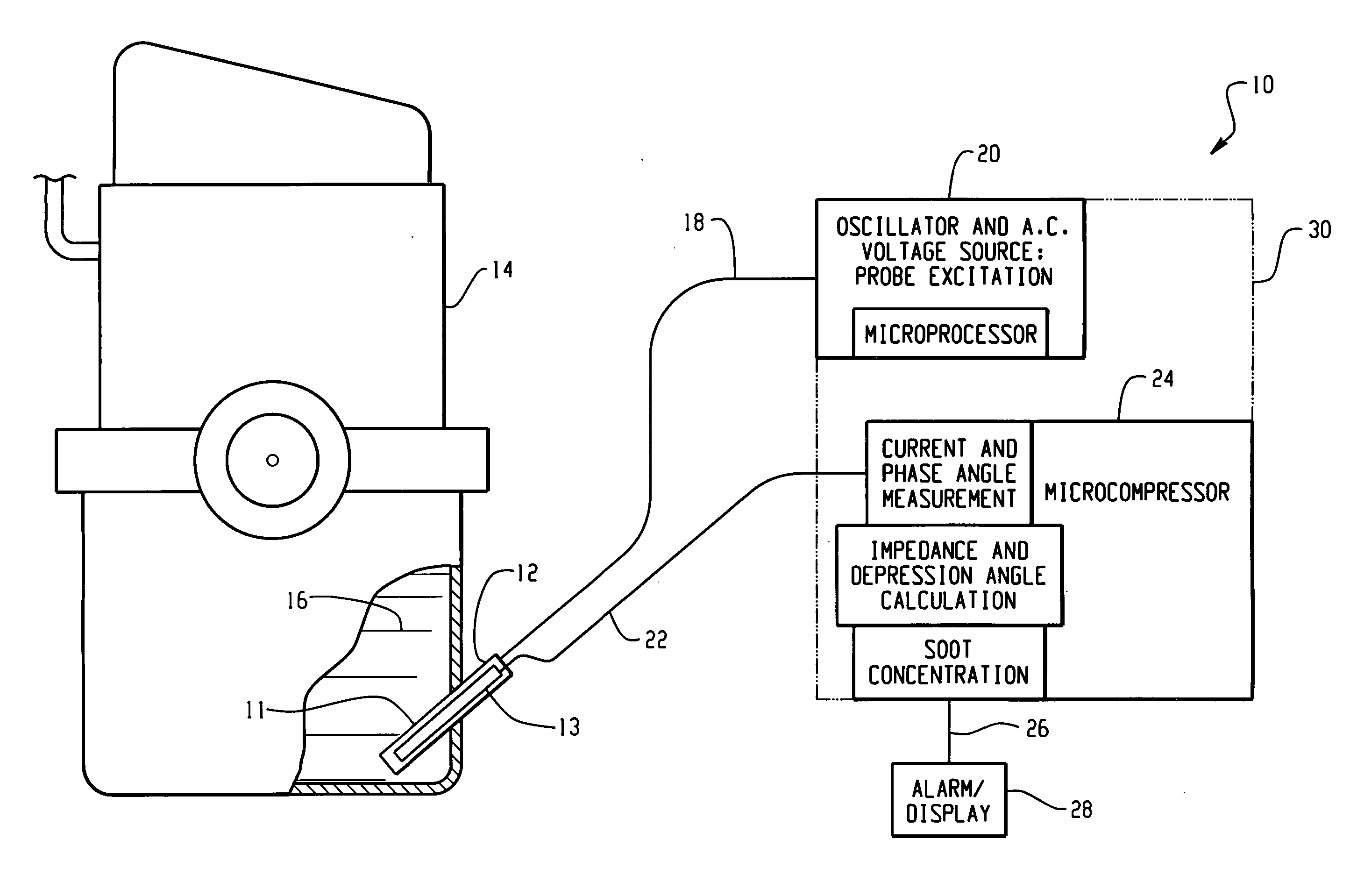
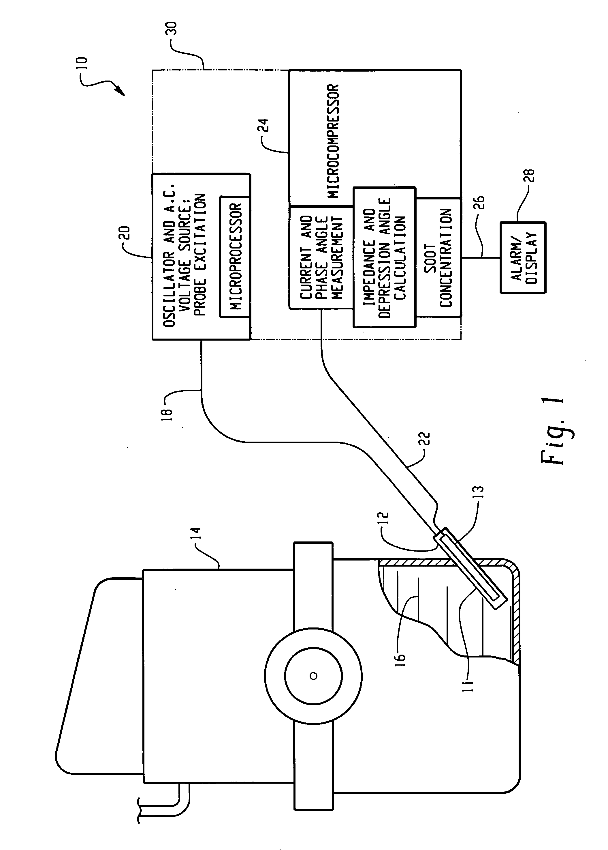
[0010] The system of the present invention is indicated generally at 10 and includes a probe 12 inserted into the crankcase or sump of a diesel engine 14 filled with lubricant to a level indicated at 16. The probe may have any suitable electrode configuration; however, in the present practice of the invention it has been found satisfactory to use a pair of concentric tubularly configured concentric electrodes denoted by reference numerals 11, 13 in FIG. 1. This probe may be configured as set forth in co-pending application Ser. No. 10 / 060,107 filed Jan. 31, 2002, entitled “Probe Assembly For Fluid Condition Monitor And Method Of Making Same” and assigned to the assignee of the present application.

[0011] The probe 12 has one electrode excited along line 18 with a relatively low voltage AC current from a controller 20 which may include an oscillator and microprocessor for providing a relatively low voltage source of AC current to the probe. The probe current measured by connection th...


PUM

PropertyMeasurementUnit
frequenciesaaaaaaaaaa
frequencyaaaaaaaaaa
frequencyaaaaaaaaaa

Abstract

A probe having a pair of closely spaced electrodes is immersed in the lubricant and one electrode is excited with a relatively low voltage AC current. The frequency is swept over a range of about 1-10,000 Hertz and the current and phase angle measured at selected frequency intervals. The reactive (Z″) and resistive (Z″) impedances are computed for each current measurement and values of Z″ plotted as a function of Z′ as a Nyquist plot. The center of curvature of the plot between the origin and the minimum value of Z″ is located; and, the angle of depression of a line from the origin through the center of curvature ⊖ is determined from the plot. Samples of lubricant having known concentration of soot are measured and the angle ⊖ determined for each sample. The angle is then plotted as a function of soot concentration and a smooth curve fitted to the data plots. The curve may be programmed into a microcomputer to be used with the sensor for real time determination of soot concentration.

Description

BACKGROUND OF THE INVENTION [0001] The present invention relates to detecting the accumulation of soot or carbon particles in diesel engine lubricant. It has been found that recent reductions in mandated limits for vehicle engine exhaust emissions have required fitting diesel engines for use with exhaust gas recirculation (EGR) valves to dilute the fuel-air charge ratio. This has resulted in changes in combustion chemistry and an increase in the rate of build-up of soot blowing past the engine piston rings and contaminating the engine lubricant oil. [0002] The presence of soot above a threshold concentration has been found to render the engine lubricant unable to effectively perform its function and engine damage becomes imminent. [0003] Heretofore, available means for determining soot concentration in engine lubricant were laboratory techniques which required taking a sample of the engine oil to a laboratory for analysis and performing Thermo Gravimetric Analysis or using optical t...

Claims


Application Information

Patent Timeline
Patent Type & Authority Applications(United States)
IPC IPC(8): G01N27/02F01M11/10G01N33/28G01R27/26
CPCG01N33/2888G01N27/02
Inventor KOEHLER, CHARLES J.HIRTHE, RICHARD W.SEITZ, MARTIN A.
Owner EATON CORP
Why Eureka
Try Eureka