Liveness protocol

a protocol and liveness technology, applied in the field of liveness protocols, can solve the problems of frequent changes in topology, low reliability of wireless networks, and low bandwidth, and achieve the effects of limited processing and memory capabilities of devices, low reliability, and low bandwidth

Inactive Publication Date: 2005-01-27
INTEL CORP +1
View PDF18 Cites 61 Cited by
  • Summary
  • Abstract
  • Description
  • Claims
  • Application Information

AI Technical Summary

Problems solved by technology

Wireless networks may have low reliability, low bandwidth, and frequent changes in topology.
The devices may have limited processing and memory capabilities.

Method used


Image

  • Liveness protocol
  • Liveness protocol
  • Liveness protocol

Examples


Embodiment Construction

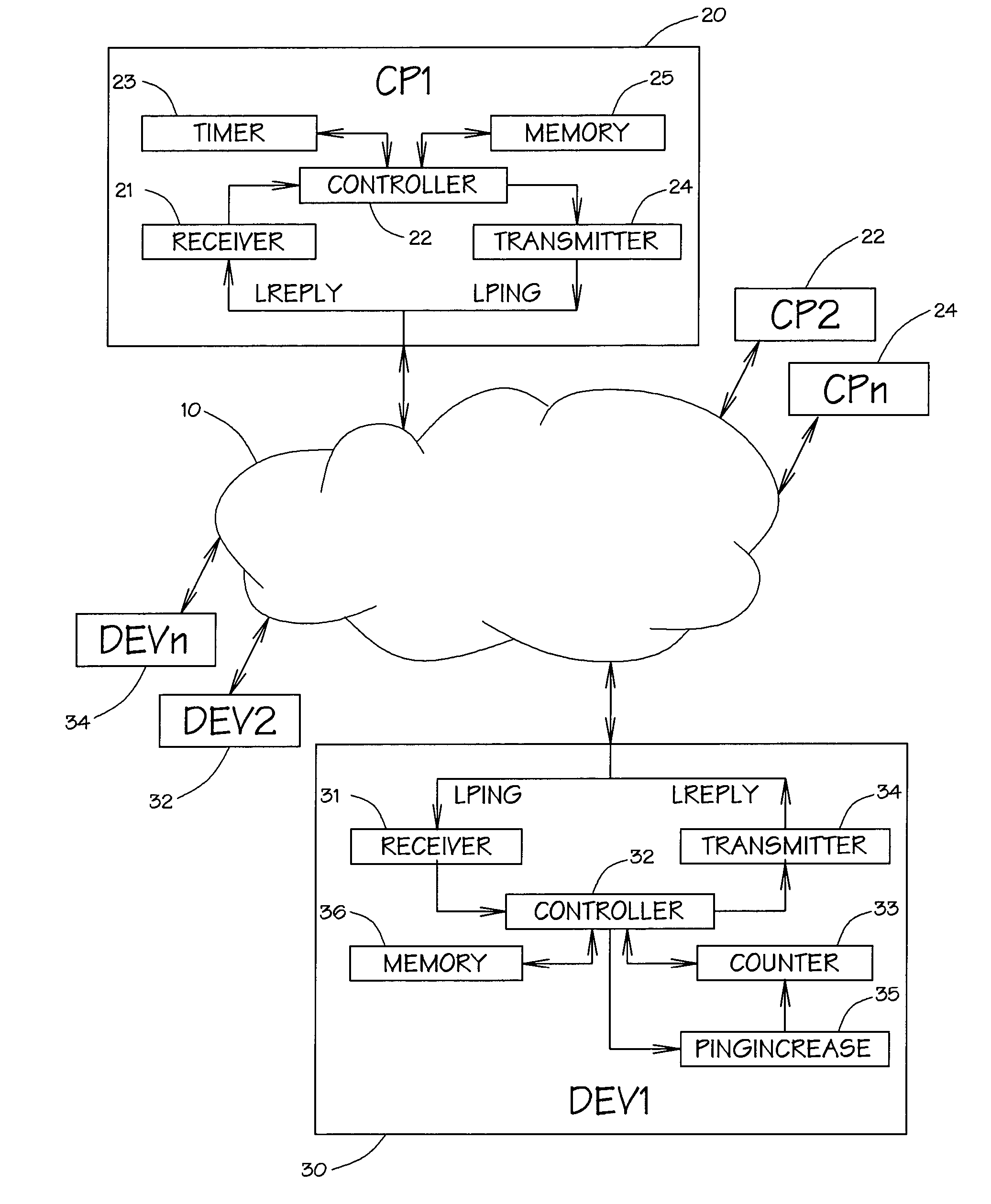
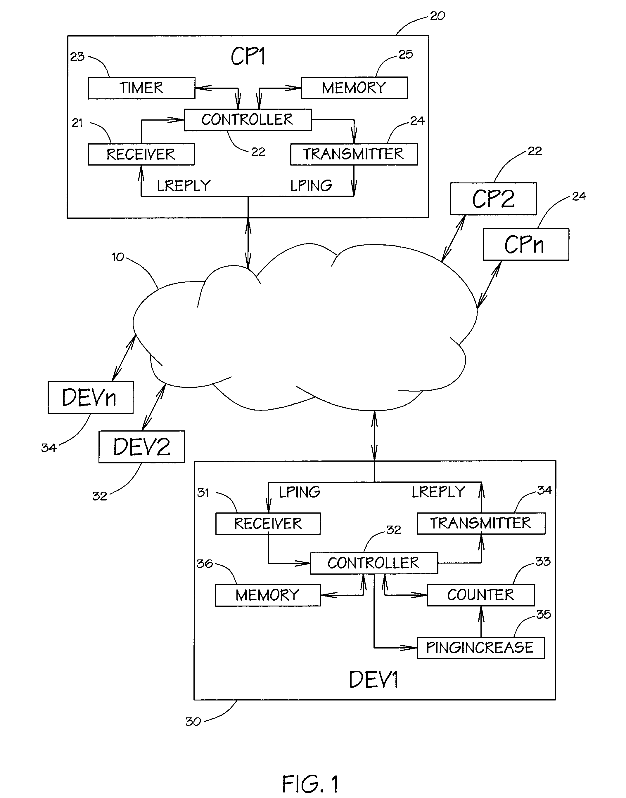
A Liveness Ping Protocol may be defined for a network 10 that includes clients 20 and devices 30 as shown in FIG. 1, such as a UPnP™ (a certification mark of the UPnP Implementers Corporation) network. The Liveness Ping Protocol may allow clients 20 to determine what devices 30 are reachable while controlling the overhead of the protocol on each device. If a client 20 wants to check a particular subset of devices 30, it may start a session of the Liveness Ping Protocol for each device to be checked. Clients 20 may be able to change that subset at will. A client may not be forced to use Liveness Ping Protocol. In an exemplary embodiment, the subset of devices may be allowed to be empty.

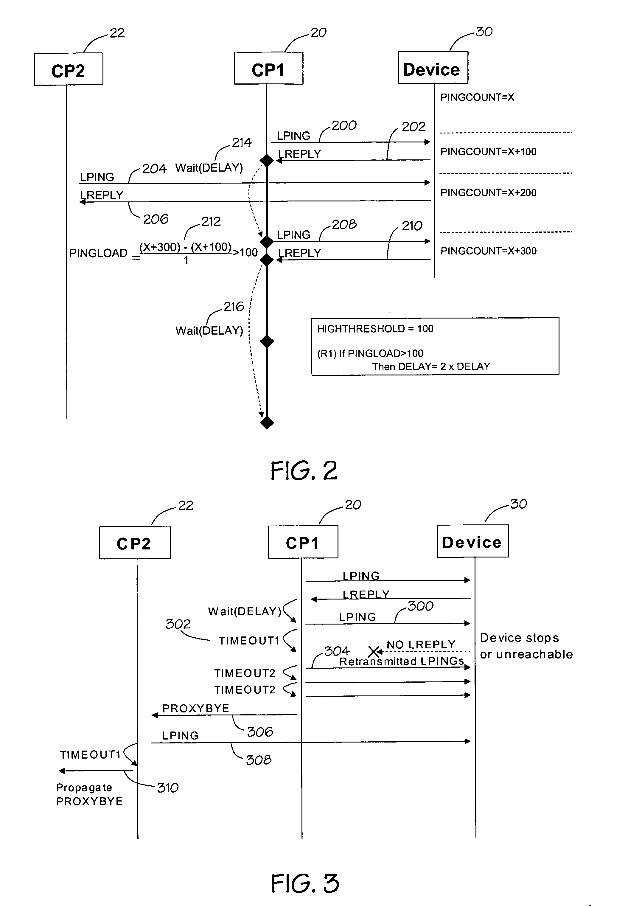
A client may check for the presence of a device by sending an LPING message, which may be sent using unicast User Datagram Protocol (UDP). The device may reply with an LREPLY message, which may be in a UDP unicast packet. If the client does not receive a reply before a timeout, it may retransmit the L...


PUM


Abstract

A network includes a connected device and a connected client. The device includes a receiver to receive ping messages, a counter to count the ping messages received, and a transmitter to transmit a reply message that includes a ping load value that is responsive to the count value. The client includes a timer to measure a delay time, a transmitter to transmit a ping message to the device after the delay time has elapsed since transmitting a previous ping message to the device, a receiver to receive the reply message, and a controller to adjust the delay time responsive to the device ping load.

Description

BACKGROUND OF THE INVENTION Networks may provide connectivity among stand-alone devices and personal computers (PCs) from many different vendors. A network may include a multitude of devices including those in the productivity domain (like desktop PCs, printers, and scanners), the entertainment domain (like televisions and audio sets), home control (like lighting and thermostat control), and the mobile domain (like laptops, universal remote controls, mobile phones, and personal digital assistants). These devices may be removably connected to the network to create a network with a dynamic configuration and transient reachability of devices. One such network is a UPnP™ (a certification mark of the UPnP Implementers Corporation) network. To reduce or eliminate the requirement for network administrators, devices added to a network may be “plug and play”. There may be seamless roaming of devices between different networks. The number of devices may range from a few to thousands in a si...

Claims


Application Information

Patent Timeline
Patent Type & Authority Applications(United States)
IPC IPC(8): H04L29/06H04L29/08
CPCH04L67/22H04L69/329H04L69/164H04L69/16H04L67/535H04L12/28H04L65/40
Inventor ELLISON, CARL M.BODLAENDER, MAARTEN PETERGUIDI, JARNO
Owner INTEL CORP
Why Eureka
Try Eureka