
Video mail server with reduced frame loss

a video mail server and frame loss technology, applied in the field of video telephony, can solve the problems of loss of all subsequent frames that depend on them, loss of the entire frame, and further exacerbated frame loss

Active Publication Date: 2005-01-27
INNOMEDIA PTE
View PDF9 Cites 33 Cited by
  • Summary
  • Abstract
  • Description
  • Claims
  • Application Information

AI Technical Summary

Benefits of technology

[0032] In response to receiving a lost frame message, the video codec may compress the next image frame of the motion video images as an independent frame to reduce freeze frame time at the user system.

Problems solved by technology

A problem with interdependent frames is that if a frame is lost during transmission, all subsequent frames that depend thereon are also lost.
Frame loss is further exacerbated by the fact that each image frame can be transmitted in multiple RTP packets.
Loss of any RTP packet will cause the loss of the entire frame.
A problem exists in that implementing a video mail server causes the video message to be transmitted twice.
Frames can be lost in the transmission from the caller to the voice mail server resulting in freeze frame periods stored on the voice mail server.

Method used


Image

  • Video mail server with reduced frame loss
  • Video mail server with reduced frame loss
  • Video mail server with reduced frame loss

Examples


eighth embodiment

[0084] An eighth embodiment includes establishing both the first internet protocol channel 18 and the second internet protocol channel 20 as a TCP / IP channels. As such the IP services module 32 will operate TCP / IP error correction on both channels 18 and 20 to ensure that there are no lost frames during either the recording session or the playback session.

[0085] Signaling Client.

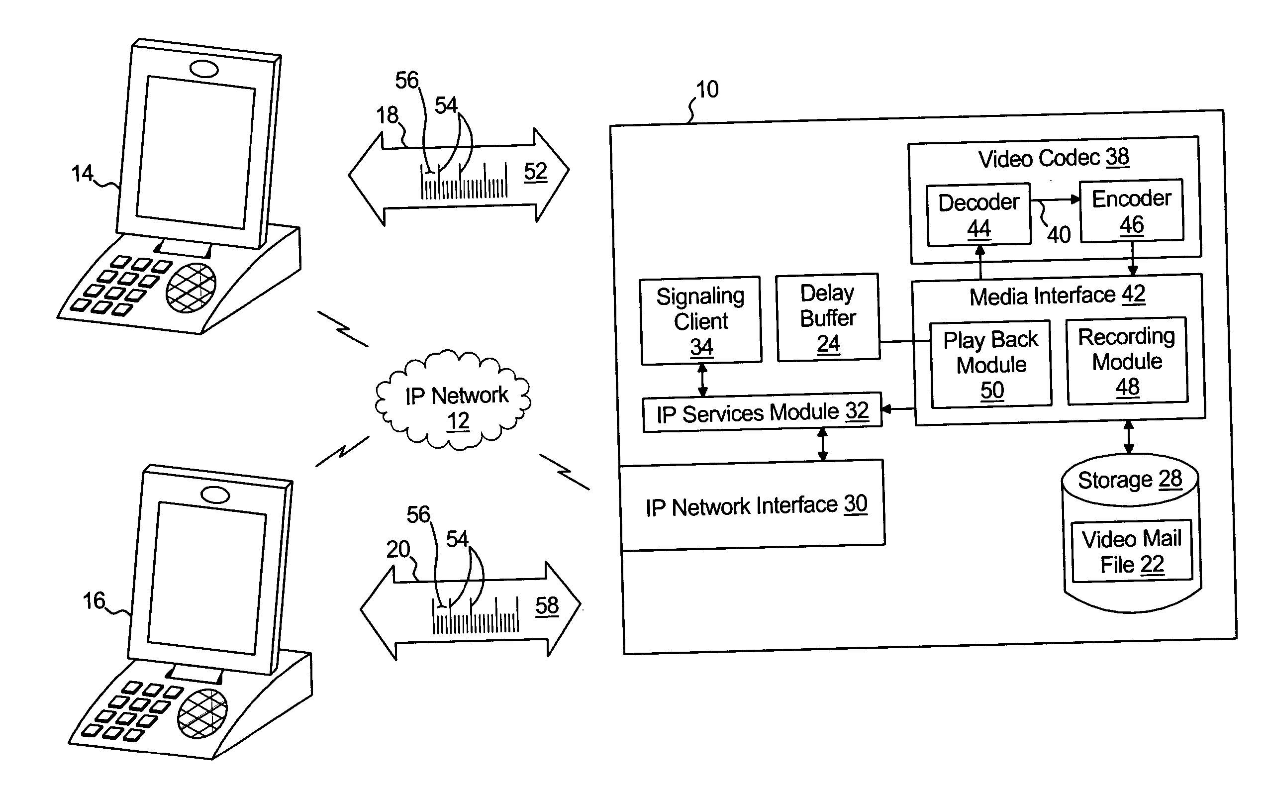
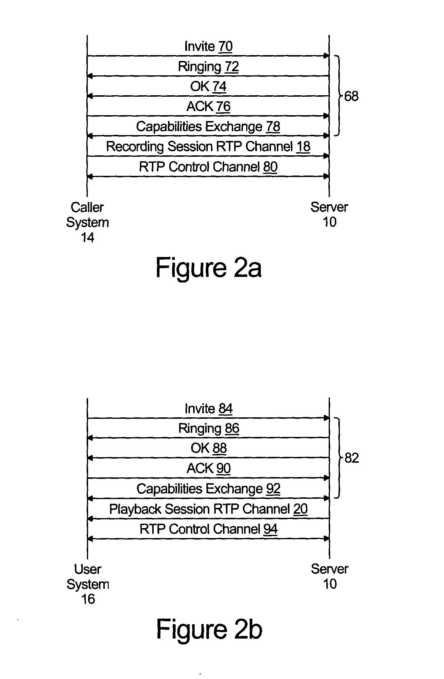
[0086] The ladder diagram of FIG. 2a represents interaction between the server 10 and the caller system 14. Referring to FIG. 2a in conjunction with FIG. 1, steps 68 represent the signaling module 34 establishing the first internet protocol channel 18 with the caller system 14. As discussed above, the SIP signaling described herein is for purposes of illustration only and is not intended to limit the scope of the invention to only those systems that implement SIP.

[0087] Step 70 represents the signaling module 34 receiving an invite message from the caller system 14 (or a proxy representing the caller syste...

first embodiment

[0093] operation of the media interface is illustrated with referring to the flow chart of FIG. 3a, the flowchart of FIG. 4b, and the frame diagram of FIG. 5a in conjunction with FIG. 1. The flow chart of FIG. 3a represents operation of the recording module 48 of the media interface 42. The flowchart of FIG. 4b represents operation of the playback module 50 of the media interface 42, and the frame diagram 5a represents the play back sequence of image frames 58.

[0094] With reference to FIG. 3a and FIG. 1, the recording module receives each frame 54 and 56 of the recording sequence of compressed image frames 58 from the caller system 14 over the first IP channel 18, as is represented by step 126, and stores each received frame 54 and 56 as the video mail file 22 in the storage. The endless loop between steps 126 and 128 represents receipt and storage of each frame 54 and 46 in the sequence.

[0095] With reference to FIG. 4b and FIG. 1, the playback module simultaneously operates three ...

third embodiment

[0109] The third process includes determining whether an event has occurred at step 108 and, if so, generating a signal to the encoder module 46 to generate the next frame in the playback sequence of compressed image frames 58 as an independent format frame 54. In this third embodiment, the event that would trigger such a signal would be receipt of a lost frame message 36 from the user system 16 indicating that a frame loss has occurred. As such, the resultant playback sequence of compressed image frames 58 includes an independent frame 54 following each lost frame message 36.


PUM


Abstract

A video mail server comprises a video call signaling module coupled to an internet protocol network for establishing a first internet protocol channel with a caller remote internet video device to support a recording session over the internet protocol network and establishing a second internet protocol channel with a user remote internet video device to support a playback session over the internet protocol network. A media interface comprises a recording module for obtaining a recording sequence of compressed images representing motion video images from the caller remote internet video device and storing a video mail file representing the recording sequence of compressed images. Each compressed image frame is one of: i) an independent frame from which an image frame can be recovered utilizing only the independent frame; and ii) a dependent frame from which the image frame can only be recovered utilizing both the dependent frame and an independent frame preceding the dependent frame in the sequence. A play back module retrieves video mail file from the storage and transfers a playback sequence of compressed images to the user remote internet video device.

Description

TECHNICAL FIELD [0001] The present invention relates to video telephony, and in particular to a video mail server and methods for recording and playing back video mail messages. BACKGROUND OF THE INVENTION [0002] For quite some time telephone systems, including both private telephone systems, wireless telephone service provider systems, and PSTN service provider systems have included voice mail systems. [0003] The voice mail functions of a telephone system are typically provided by a voice mail server. Upon the occurrence of certain events, such as a telephone line being busy or unanswered, the telephone system will signal the call (in a process typically referred to as roll-over” to the voice mail server. The voice mail server will receive the telephone call thereby opening a recording session. [0004] During the recording session, the voice mail server will prompt the caller to leave a message, capture the audio stream from the caller, and store the captured audio stream for subseq...

Claims


Application Information

Patent Timeline
Patent Type & Authority Applications(United States)
IPC IPC(8): H04L12/58H04L29/06H04M3/53
CPCH04L12/58H04L29/06027H04L65/608H04N7/173H04N21/4786H04M3/5315H04L65/65H04L51/10H04L51/00H04L65/1101
Inventor ZHU, YUESHENGYU, SHAUNLEE, CHIH-PING
Owner INNOMEDIA PTE
Learn More