System and method for delayed priority boost

Active Publication Date: 2005-01-27
IBM CORP
View PDF21 Cites 30 Cited by
  • Summary
  • Abstract
  • Description
  • Claims
  • Application Information

AI Technical Summary

Benefits of technology

[0013] It has been discovered that the aforementioned challenges are resolved using a system and method that boosts a thread's priority when the thread is about to be preempted. In this manner, if the thread w

Problems solved by technology

A challenge of this approach, however, is that the thread takes time to request the priority level changes (both to boost and un-boost) and also requires the services of and further burdens the operating system.
However, many processes cannot risk the chance that their thread will be preempted during a critical section, so the process boosts and un-boosts the thread's priority.
However, even a small priority boost is costly in t

Method used


Image

  • System and method for delayed priority boost
  • System and method for delayed priority boost
  • System and method for delayed priority boost

Examples


Embodiment Construction

[0025] The following is intended to provide a detailed description of an example of the invention and should not be taken to be limiting of the invention itself. Rather, any number of variations may fall within the scope of the invention, which is defined in the claims following the description.

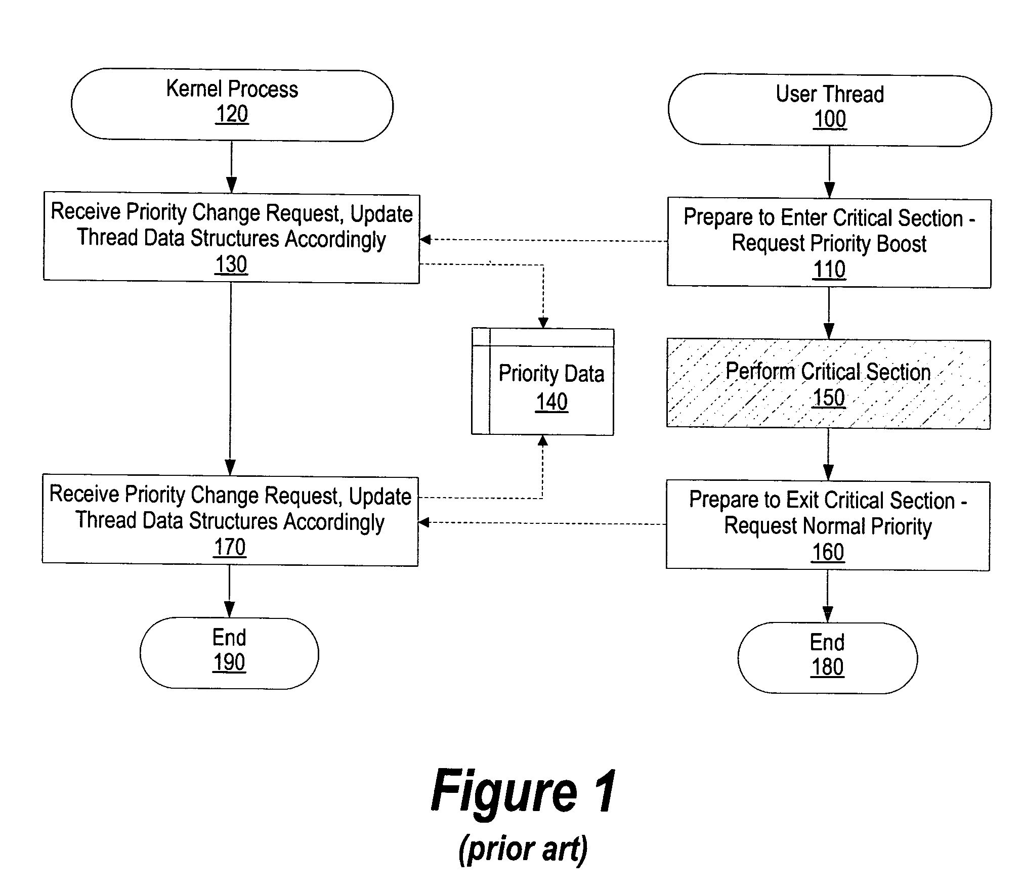
[0026]FIG. 1 is a high level flowchart showing how priority boosts are handled in prior art systems when a thread enters a critical section. For details regarding FIG. 1, see the description provided in the “background” section, above.

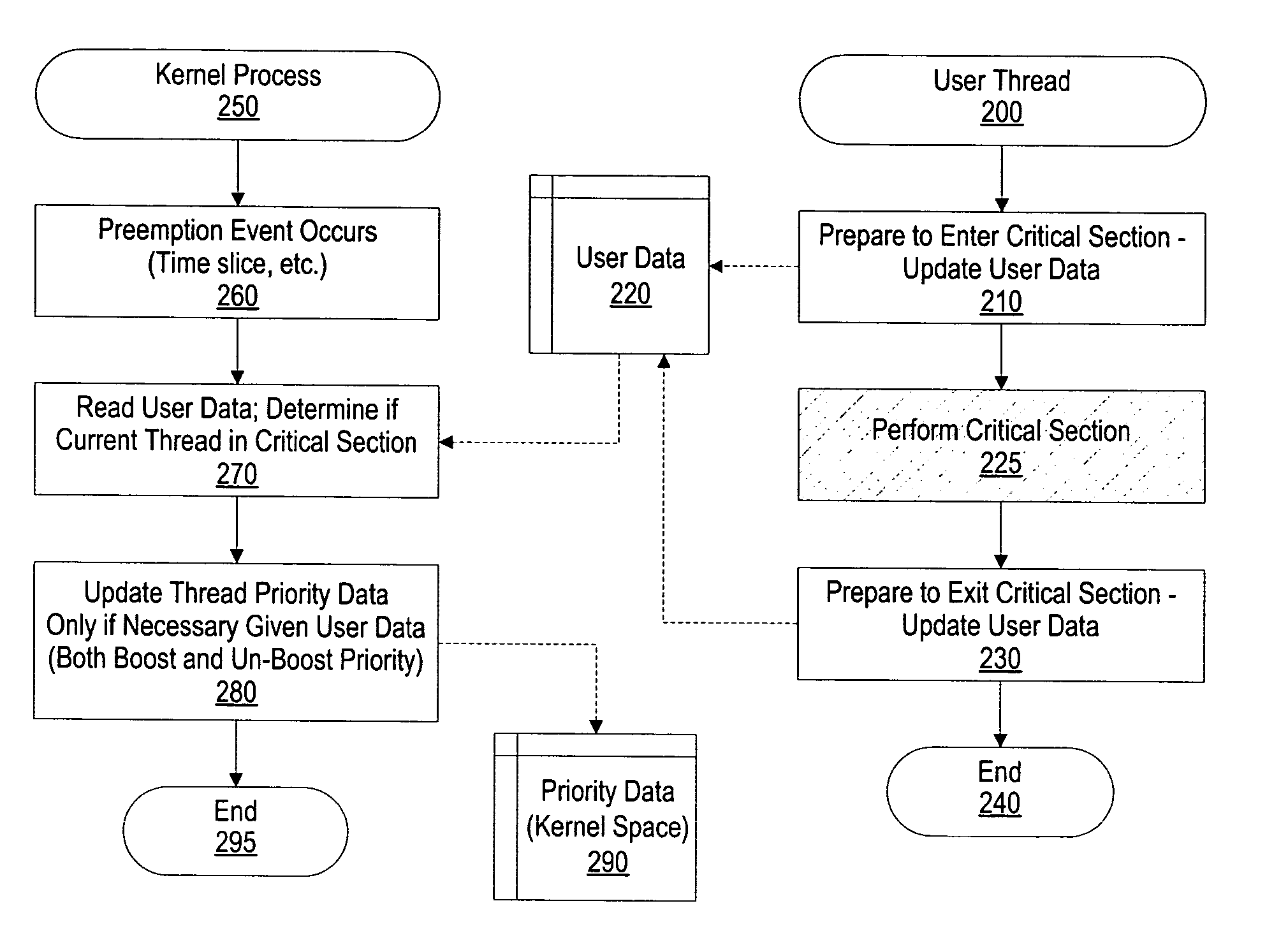
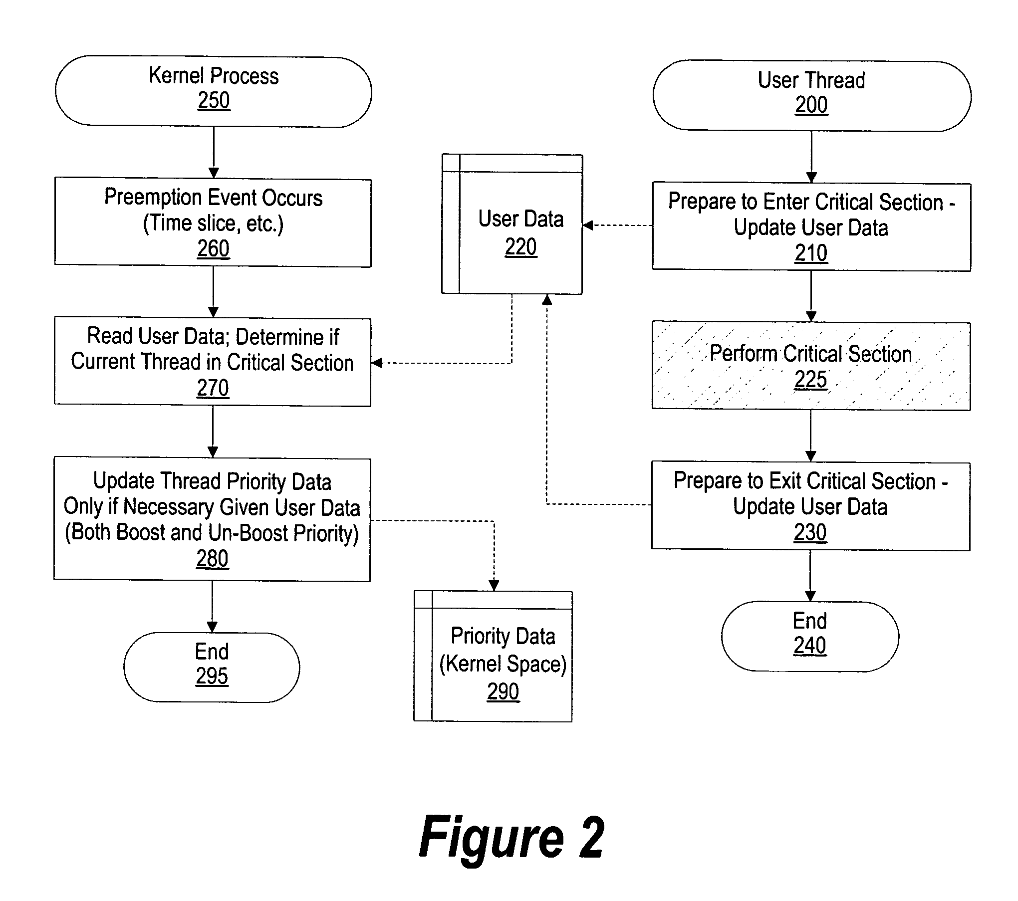
[0027]FIG. 2 is a high level flowchart showing steps taken in performing a delayed priority boost. User thread processing commences at 100 whereupon, at some point, the thread prepares to enter a critical section of code. At step 210, the user thread prepares to enter the critical section of code by updating user level data structure 220, such as a user level structure that includes information about system locks. After writing data to the user level data stru...


PUM


Abstract

A system and method is provided for delaying a priority boost of an execution thread. When a thread prepares to enter a critical section of code, such as when the thread utilizes a shared system resource, a user mode accessible data area is updated indicating that the thread is in a critical section and, if the kernel receives a preemption event, the priority boost that the thread should receive. If the kernel receives a preemption event before the thread finishes the critical section, the kernel applies the priority boost on behalf of the thread. Often, the thread will finish the critical section without having to have its priority actually boosted. If the thread does receive an actual priority boost then, after the critical section is finished, the kernel resets the thread's priority to a normal level.

Description

BACKGROUND OF THE INVENTION [0001] 1. Technical Field [0002] The present invention relates in general to a system and method for delaying a priority. boost for a processing thread. More particularly, the present invention relates to a system and method to boost certain threads only when the thread is about to be preempted. [0003] 2. Description of the Related Art [0004] Modern computer systems perform multiple tasks seemingly at the same time. Using multitasking, the processor handles instructions from multiple processes by servicing the processes in a round-robin fashion. In this manner, a process is executed by the processor for a small amount of time before it is time sliced, it's settings and register values saved, a different process is executed by the processor. These processes, or “threads,” are a stream of instructions corresponding to one or more software applications that require handling by the processor. The terms “process” and “thread” are used herein interchangeably to...

Claims


Application Information

Patent Timeline
IPC IPC(8): G06F9/46
CPCG06F9/52G06F9/4818
Inventor ACCAPADI, JOS MANUELDUNSHEA, ANDREWMICHEL, DIRKVAN FLEET, JAMES W.
Owner IBM CORP
Why Eureka
Try Eureka