

Susceptor for Semiconductor Manufacturing Equipment, and Semiconductor Manufacturing Equipment in Which the Susceptor Is Installed
Inactive Publication Date: 2005-02-03
SUMITOMO ELECTRIC IND LTD
View PDF1 Cites 11 Cited by
- Summary
- Abstract
- Description
- Claims
- Application Information
AI Technical Summary
Benefits of technology
[0010] The present invention has been brought about to resolve the foregoing problems. In particular, an object of the present invention is to enhance the durability of electrodes for supplying electricity to electroconductive components formed in the interior and/or on th
Problems solved by technology
A problem with this structure, however, has been that the integrity of the joint in the mechanically joined portion of the structure has been compromised by the hot/cold (thermal) cycling of the susceptor and by the corrosive gases employed inside the processing chamber.
Nevertheless, although filling the jacket with non-oxidative gas serves to prevent corrosion, a problem in situat
Method used
View moreImage
Smart ImageViewing Examples

Examples
 PUM
| Property | Measurement | Unit |
|---|---|---|
| Durability | aaaaa | aaaaa |
Abstract
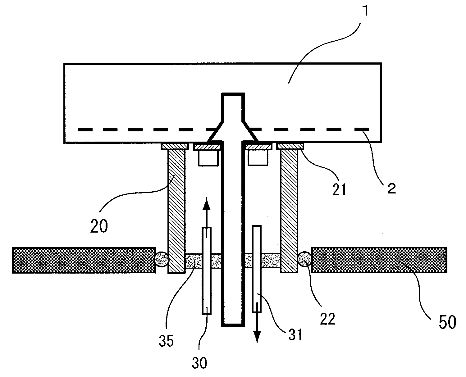
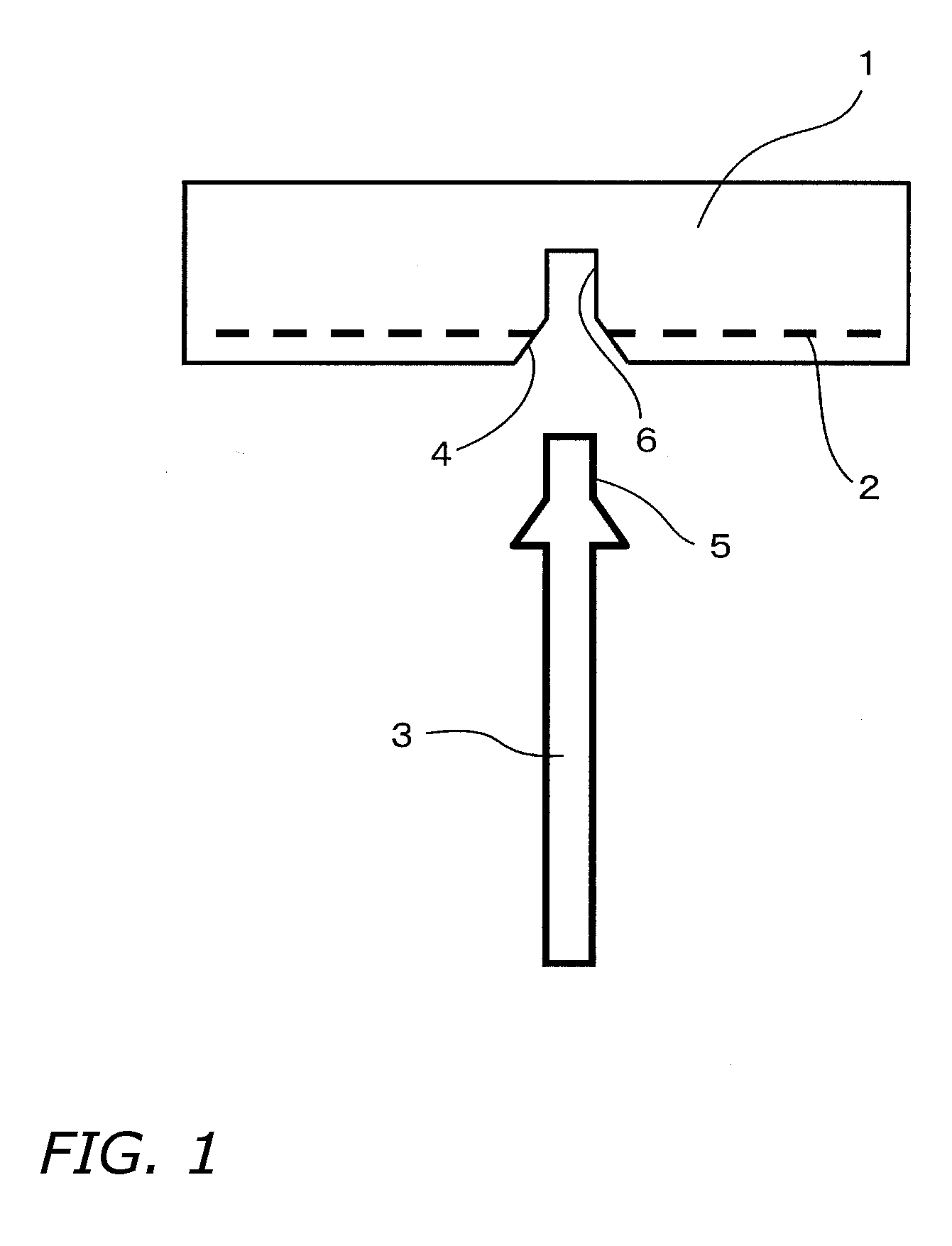
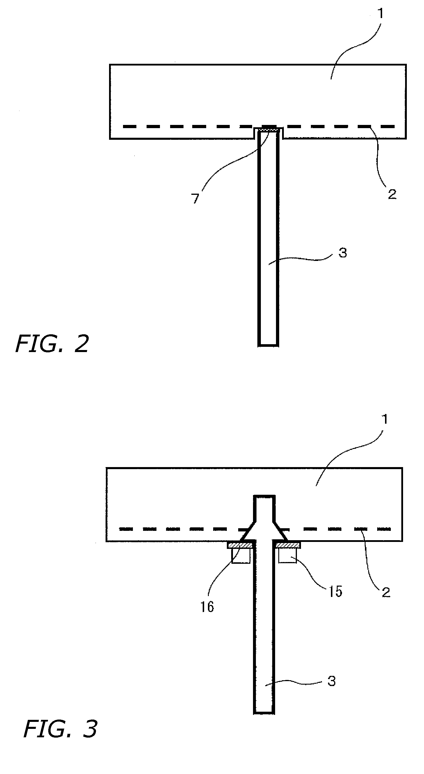
Enhances the durability of electrodes for supplying electricity to electroconductive components formed in the interior and/or on the surface of a susceptor ceramic heater-block, affords for semi-conductor manufacturing equipment a susceptor in which incidents of inter-electrode shorting are prevented, and makes available semiconductor manufacturing equipment in which the susceptor is installed. Rendering as unitary articles the electrodes for supplying electricity to electroconductive components formed in the interior and/or on the surface of a ceramic heater-block contributes to improved electrode endurance. Further, setting up a tubular piece encompassing each electrode contributes to preventing incidents of shorting. Introducing inert gas into the interior of the tubular pieces further improves the reliability of the electrodes. Semiconductor manufacturing equipment of excellent productivity and throughput can be made available by installing a susceptor of this kind into the semiconductor manufacturing equipment.
Description
BACKGROUND OF INVENTION [0001] 1. Technical Field [0002] The present invention relates to susceptors employed in semiconductor manufacturing equipment-such as devices for plasma CVD, low-pressure CVD, metal CVD, dielectric CVD, ion-implantation, etching, low-k deposition, and degassing—and furthermore to semiconductor manufacturing equipment in which such susceptors are installed. [0003] 2. Background Art [0004] Conventionally, in semiconductor manufacturing procedures various processes, such as film deposition and etching, are carried out on semiconductor substrates that are the processed objects. Susceptors serving to retain semiconductor substrates are used in the processing devices in which such processes on semiconductor substrates are carried out. [0005] As conventional susceptors of this sort, devices using a ceramic such as aluminum nitride have in recent years been proposed, and some of the proposed devices have been realized. Electroconductive components such as RF electro...
Claims
Login to View More Application Information
Patent Timeline
 IPC IPC(8): C23C16/458H01L21/02H01L21/205H01L21/265H01L21/3065H01L21/683
CPCC23C16/4586C23C16/4581
InventorNATSUHARA, MASUHIRONAKATA, HIROHIKO
OwnerSUMITOMO ELECTRIC IND LTD